Two PHOS FEE boards were used for MPC readout.
PHOS FEE reshapes analog signal from preamplifiers and digitizes
resulting analog amplitude every 10ns 115 times. Digitized samples
are used for initial amplitude and time reconstruction.
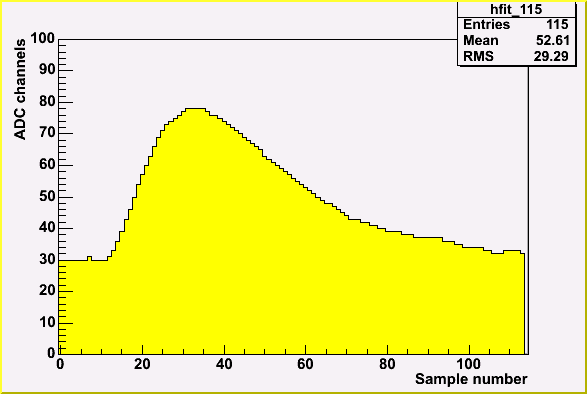
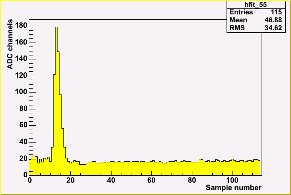
One of boards was modified in order to decrease shaper rise and decay times.
Typical samples for modified and original boards are below.

|

|
| Typical sample in original board | Typical sample in modified board |

|
|
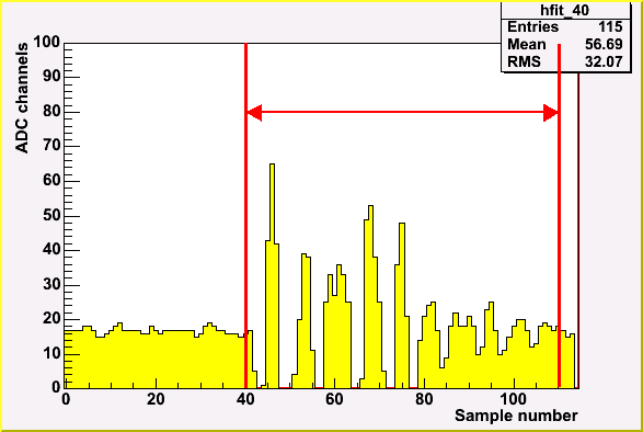
| Noise pickup in original board | Noise pickup in modified board |
 Noise start point distribution
Proposed by PHOS amplitude reconstruction proved to be non-working in our conditions.
Therefore amplitude reconstruction was performed by fitting first 7 samples with a constant
and +-3 bins around maximum sample with a parabola.

The test beam setup also picks up 50 Hz as it was found at BNL testbench.
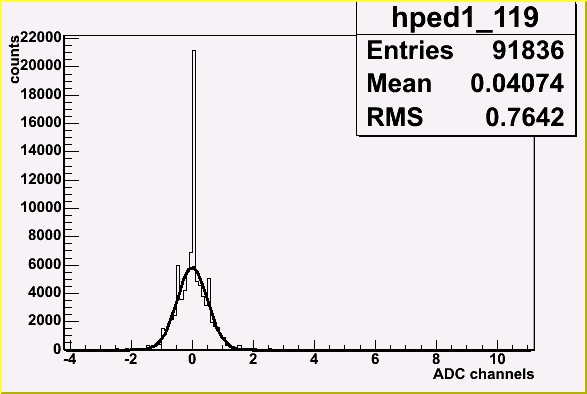
Therefore pedestal baseline floats more than it can be expected from deviation of samples
from average pedestal in one event. Due to this fact pedestals were calculated in each event.
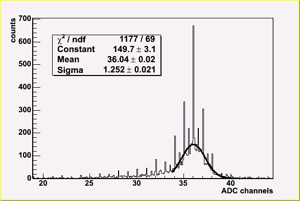
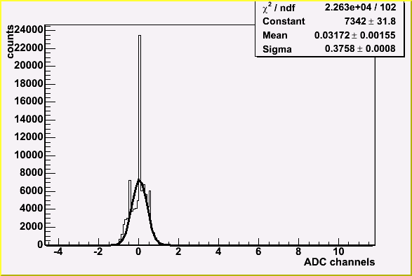
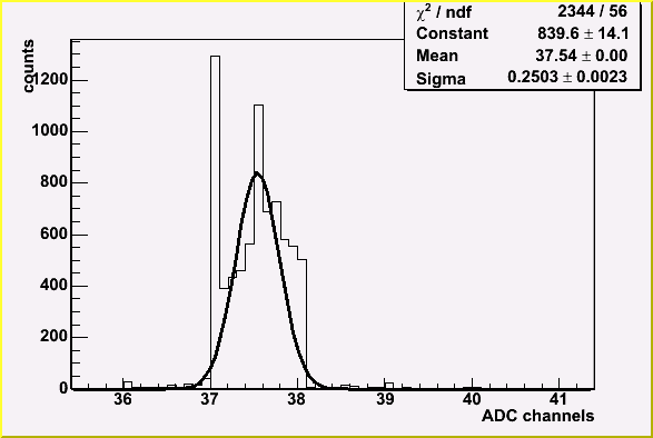
Pedestal determination error is 0.29 ADC channels for HG and 0.15 ADC channels for LG.
On the plots below is the following.
Plots on the right are distribution of average pedestal value.
Plots on the right are distribution of difference of pedestal samples and average pedestal
in a event.
|
|
| Distribution of HG pedestal samples relative to average HG pedestal in one event | Distribution of HG mean pedestal value (typical channel) |
|
|
| Distribution of LG pedestal samples relative to average HG pedestal in one event | Distribution of LG mean pedestal value (typical channel) |
 Typical reconstructed spectrum
Initially gains were set to be approximately equal using
UIUC testbench data. In UIUC tests assembled modules were lit by the same LED
and HV was chosen so that all modules give the same amplitude.
Gains were extracted using 2 steps calibration procedure on 16 GeV electrons.
Initial gain values were found by the right edge of energy spectrum in each module.
The second step was interational adjustment of gains using the position of
maximum of 3x3 energy sum around given module.
Final difference of 3x3 energy sum peak position in different modules was less than 1%.
More than 80% of modules are less than 10% off the average value.
That means that setting initial gains with LED is a good idea.
 Gain distribution
Hi/Lo ratios were extracted from the data on sample by sample basis.
The average value of HGsample/LGsample(LGsample)
was fitted by a parabola.
It is important that fitting by a line gives bad results. HiLo has a significant
curvature. It might be effect of non-linearity of HGdigital(HGanalog)
at high HG. But it might be more of interest for ALICE guys.
Below is the distribution of linear term of HiLo.
 HiLo distribution
Electrons of 4, 8, 16 and 33 GeV were used for resolution studies. No significant electron peak at 66 GeV and higher were found even after dispersion cut.

|

|

|
| 4 GeV electrons | 8 GeV electrons | 16 GeV electrons |

Resolution function was fitted with sigma/E=sqrt((a*a)/E+b*b), where a=12.3 %*sqrt(GeV)
and b=1.2%. These values are higher than expected but they include beam resolution and
temperature variation - two most significant sources of error in our case.

Calculated linearity is quite poor but again assuming beam resolution and
temperature variation it might be much better.
Hit point was reconstructed using log weights with w0=4.0.
Resulting shower shapes are below.

Electron shower shapes at 8 and 16 GeV start to differ from distance from
center of the shower of approximately 1.4 which corresponds to approximately
1% of shower energy. It can be explained by the relative noise level which is
two times higher for 8 GeV as compared to 16 GeV.

In fact it not a shape of pure hadron sample. It contains significant ammount of
misidentified electrons which contribute to the "bump" below 0.5 modules.

Aluminum converter installed in front of MPC prototype for studies of BBC influence on MPC gave not a significant increase of shower width. Average dispersion width increased by less than 1%.
Modified card is more sensitive to high frequency noise. As it appears it has a strong influence on dispersion resolution.

In modified card noise becomes larger than energy deposit starting from
distance of 0.8 modules from the center of the shower. It means that only 3
tower energies can be used for hit point and dispersion reconstruction.

 Shower shapes module-by-module in the central part of MPC prototype
 Dispersion along pricipal axes distribution in central modules of MPC prototype.