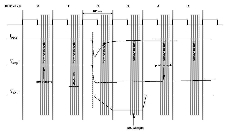
The RHIC clock tick length is 106 ns (1/106 ns=9.43 MHz). One RHIC cycle consists of 120 clocks. The goal is to have 60 bunches per ring (e.g. every other clock is empty, this is probably because of problems with air ionisation -- the electron cloud from ionized air must have enough time to dissipate before another bunch arrives). Even with 60 bunches the maximum collision frequency will be much lower, e.g. on the order of 10 KHz for AuAu, because the probability of a collision in each bunch crossing is rather small. (BTW during data anlysis we assume that there's no more than one collision per bunch crossing.) For pp the maximum collision frequency is much higher (how much?) as a result of "denser" bunches .
Each channel of the EMCal ASIC has 64 AMU (Analog Memory Unit) cells per signal type. Signal types are: low gain amplitude, high gain amplitude, and time, also known as TAC (Time-to-Amplitude Converter). Each RHIC clock there's a strobe (the strobe is relatively long, 20-50 ns (more precise number?)) that pushes the amplitude into an AMU cell (basically, charging the capacitor to a certain voltage). At the same time, the address of this cell is pushed into a FIFO pipe. The FIFO pipe contains 40 AMU cell addresses. The amplitude stored in the AMU cell whose address just popped out of the pipe is digitized if there's an accept signal, otherwise its content is discarded. Then the cell is discharged and its address is returned to the pool of available addresses. This timing diagram can help understand the process.
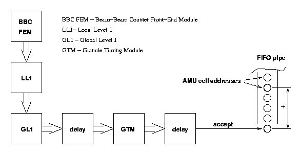
Why do we need to adjust the GL1 delay? GL1 makes a decision to read an event after a certain delay (cables, finite computation speed etc.). We have to match the accept signal with the moment when the corresponding pre sample is coming out of the FIFO pipe. After the pre sample has been digitized, the FEM knows that it has to digitize also the appropriate post sample (4 clocks later, the TAC sample is digitized 3 clocks later than the pre sample, these numbers were once established experimentally). Here's a (greatly oversimplified) diagram, that can help understand the decision making process.
To change the GTM delay you will need to edit the GTM config file (for PbGl currently it's /export/software/oncs/online_configuration/GTM/GTM.pbgl_init, this is a human-readable ASCII file) and compile it:
> make GTM.emc_init.gtm
Make didn't work for me, so I just manually ran MBParce on a linux PC
as phoncs:
> $ONLINE_MAIN/bin/MBParce GTM.pbgl_init
> GTM.pbgl_init.gtm
The actual GTM config file is specified in the corresponding granule configuration
(.pcf, Partition Configuration File, it really should be Granule Configuration
File) file ($RC_HW_CONF/emc.e.bottom.pcf for PbGl).
This is also an ASCII file that can be edited by humans.
The GTM can raise an FEM busy signal after 1, 2, 3, 4, or 5 events were accepted for digitization (this can be configured via the GTM GUI (and the GTM config file?)). At present busy is raised after 1 event has been accepted. This means that event integrity can be tested looking at pre and post sample AMU cell addresses. If
Addresspost-Addresspre!=4,
then this event should be discarded. If we accept more than 1 event at
a time for digitization, this method can be no longer applied. AMU cell
digitizing takes about 40 µs. For this period this AMU cell is not
returned to the pool.
M.Volkov,