 Application of MEDM in HV Testing
General:
 Application of MEDM in HV Testing

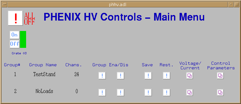
From this window can be seen several useful features of MEDM that have been implemented in our testing process. Up to eight mainframes can be controlled for this window. For each mainframe, an HV ON/OFF button set and power indictator bar is drawn, allowing the HV to be toggled for each main frame seperately ( in this case, only one mainframe is present, labeled 'Crate 03'). The HV to every mainframe can be turned off via the ALL OFF button. The Power indicator bar turns green for HV ON, yellow for HV OFF and red for a PANIC OFF condition.
Note: Recently (28 May 1999), a new button was added to the top of the interface, near the 'ALL OFF' button. The new button, added at the behest of sub-systems for the Engineering Run, disables all channels controlled by the interface.
Other than the 'Voltage/Current' and 'Control Parameters' buttons (which summon other windows), there are a set of four command buttons (marked with a !) for each group of channels. These buttons interact with the Backup and Restore utility (BURT), a program which enables a series of values to be sent into specified EPICS records, or a series of record values to be recorded. The buttons, when pressed, cause a specific .csh script to be run, which in turn calls BURT to save or restore specific values. The record fields to be saved are specified in a .req file; this is a simple ASCII file which simply lists EPICS record fields. When a backup is ordered, BURT takes this file as input and outputs the saved values taken from these records to a snapshot file (.snap) which is usually named according to the date and time at which it was taken. BURT can also be used to restore values to setable EPICS fields -- the standard MEDM interface uses several pre-existing snapshot files to change several parameters simultaneously. For example, the 'Group Enable/Disable' buttons cause a certain .snap file to be loaded, which sets the Channel Enable fields of the channels to 1 or 0, respectively. The interface also includes two command buttons to 'Save' and 'Restore'. The 'Save' button records all of the parameter values which are settable in a new .snap file. The 'Restore' button restores the settings to the values contained in a default .snap file. Both buttons can be used the access the BURT utility GUI directly (for advanced users only).
Each channel of HV can be assigned to one of many groups (in this case their are two groups, TestStand and NoLoads, to which 24 and zero channels have been assigned respectively). The Group Enable/Disable buttons allow the user to disable or enable all fo the channels in that group simultaneously. The Save and Restore buttons allow the user to store a particular group configuration or call up a previous one. The Voltage/Current and Control Parameters sub-windows can be summoned via their respective buttons.
Graphical depictions of the Sub-windows can be found under Voltage/Current and Control Parameters.
From these windows, the various HV channel properties can view and set. Some modules, such as the 1469 and the 1471, have slightly different formats in these windows. For example, in the 1469, only the bulk supply channels have a Demand Voltage property, so this field doesn't appear for the other channels. The 1471 has three properties that no other module has (Peak Current, Peak Current Trip and Ramp Trip Enable), so these columns are blank for anything other than a 1471.
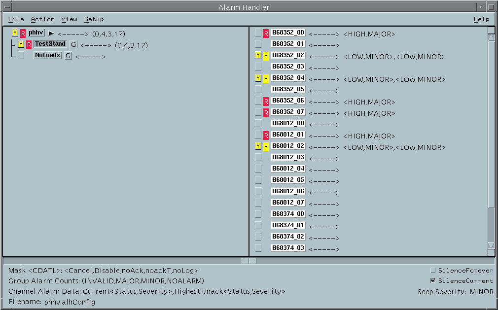
The ALH is given an alarm configuration file as input -- this file, phhv.alhConfig, is generated by the same process that generates the MEDM .adl files. The ALH windows are shown below:


Pushing the button brings up the ALH expanded window shown above. From here, a user can acknowledge alarms by channel, group or mainframe, and navigate over the channels via the buttons on the left hand side of the window. Acknowledging alarms is done by clicking the first of two red, yellow or white squares next to the channel group or mainframe label. Clicking this area causes the 'acknowledge square' to change back to neutral gray, while the second 'current status' square remains red/yellow/white until the alarm condition has been removed. Acknowledging all current alarms disables the alarm beeping. In the picture above, the Red alarms have been acknowledged and the Yellow alarms have not.
The Alarm Handler logs all alarms and operations in one of two ASCII files, called ALH-default.alhAlarm and ALH-default.alhOpmod. These files can be viewed from the Alarm Handler via the 'View' menu bar item, or can be viewed seperately by any standard text editor. The .alhAlarm file records every alarm and the time it occured. The .alhOpmod file records any operation of the Alarm Handler, such as when it was started and when alarms were acknowledged.