Performance of the MuID Blue-Logic Trigger for the
First p+p Run
H.D. Sato,
A
coarse-segmented trigger system called MuID Blue-Logic Trigger was used to
trigger muons in the South Muon Arm during the first p+p run in December 2001
and January 2002.
System overview
and basic performances such as trigger rates and efficiencies will be described
below.
1. Introduction
In p+p
collisions at RHIC, a good trigger is a key issue for the PHENIX[i]
Muon Arm since the physics trigger rate (dominated by decay pions and kaons) is
roughly 1/2000 for one Muon Arm compared to the minimum-bias trigger rate.
Originally we
had a plan to use the MuID Local-Level-1 (LL1) trigger which has an algorithm
similar to the offline road-finder, but we could not make it for this first p+p
run. We have come up with an alternative trigger system, which is much simpler
and coarse, but has enough rejection power for this run. It is called
Blue-Logic Trigger (or BLT) since NIM and CAMAC modules are used to make the
trigger logic.
The next
section describes the overview of the system design followed by summary of
performances such as trigger rates and trigger efficiencies.
2. System Overview
Figure 1 shows a schematic view of the BLT.
Figure
1: Schematic view of the MuID Blue-Logic Trigger
The input of the
BLT is 64 pseudo-trigger signals from the MuID ROCs. The output is 5 trigger
bits going into the RBIB board which is the interface into the Global-Level-1 (GL1)
decision for non-Local-Level-1 signals. The whole MuID is divided into 4
quadrants, each of which issues 'Deep' or 'Shallow' trigger, and finally the
number of fired quadrants at each depth is counted.
2.1
ROC pseudo-trigger output
|
10xx |
01xx |
01xx |
10xx |
|
10xx |
01xx |
01xx |
10xx |
Figure 2a:
Segments of ROC (solid line) and pseudo-trigger output (dashed line) for each
gap for vertical channels. Their bit assignments are shown altogether.
|
xx10 |
xx10 |
|
xx01 |
xx01 |
|
xx01 |
xx01 |
|
xx10 |
xx10 |
Figure 2b:
Segments of ROC (solid line) and pseudo-trigger output (dashed line) for each
gap for horizontal channels. Their bit assignments are shown altogether.
|
1010 A |
0110 6 |
0110 6 |
1010 A |
|
1001 9 |
0101 5 |
0101 5 |
1001 9 |
|
1001 9 |
0101 5 |
0101 5 |
1001 9 |
|
1010 A |
0110 6 |
0110 6 |
1010 A |
Figure 2c: Overlay of figure 2a and figure 2b. Bold lines represent borders of quadrants.
Each MuID ROC has 96 channels (nominally) and reads out a strip of tubes (either horizontal or vertical) roughly equal to one-fourth of a gap. This is indicated for ROCs that read out vertical (horizontal) tubes in the solid-boundary regions in figure 2a (2b) above. Each ROC has two TTL “pseudo-trigger” outputs (PS0 and PS1) that are the logical or of many input signals. For a ROC reading horizontal tubes the bits have the following meaning:
- PS0 – all East Large panel and Small Panel inputs for that ROC.
- PS1 – all West Large panel and Small Panel inputs for that ROC.
For a ROC reading vertical tubes the bits have the following meaning:
- PS0 – all Lower Panel inputs for that ROC.
- PS1 – all Upper Small Panel inputs for that ROC.
This is illustrated by the dashed lines in figures 2a and 2b above.
All output
signals were checked and confirmed to be working fine before finalizing the
trigger configuration (Run #37939).
2.2 Trigger Logic and MLU (Memory Lookup Unit)
There are a total of 80 pseudo-trigger bits (16 per gap). It was not practical to have more than 64 inputs into the trigger algorithm due to hardware limitations in available modules. Therefore we only used the 16 bits from each of four gaps. The 16 bits from each gap are split into four groups of 4 bits – each group provides the input from a particular quadrant (because of the radial MMS field real tracks from the vertex will essentially not cross quadrant boundaries). The hit pattern from each quadrant can therefore be represented as a 16-bit address (four quadrant bits from each of the four used gaps). The 16 bits from each quadrant are converted to ECL and daisy-chained into two LeCroy 2372 Memory Lookup Units (MLUs) (for deep and shallow tracks) which output a programmed 1-bit (yes/no) output corresponding to the 16-bit pseudo-trigger input address.
The text in figures 2a and 2b above show the bit assignments of each pseudo-trigger bit within the nibble (4-bits) corresponding to a particular quadrant/gap. Note that the bits in different quadrants go to different MLUs (different 16-bit words) and can therefore have identical bit assignments. If there is a real track one expects both horizontal and vertical tubes to be hit. There are four different two-bit patterns in each quadrant corresponding to single tracks – this is illustrated in the text in figure 2c above which is obtained by overlaying figures 2a and 2b.
The nibbles from each gap for a particular quadrant are collected into a 16-bit address. If gap-0 is the most significant nibble then a track going straight through the upper-west piece of the upper-west quadrant would fire the address 0xAAAA in the upper-west MLUs. A track in the upper-central piece of the same quadrant will fire 0x6666 and a track crossing from the upper-central piece to the upper-west piece might fire 0x66AA (depending on which gap it crosses).
The allowed addresses for tracks originating from the vertex are listed in table 1 below. Each pattern has 8 bits on, corresponding to horizontal and vertical hits in each gap. Either 6 or 7 of these bits are required to fire (depending on the number of missed hits allowed). All other bits are treated as “don’t care”, i.e., any number of additional hits is allowed.
|
0x5555 |
0x6666 |
0x9999 |
0xAAAA |
|
|
0x5556 |
0x5559 |
0x555A |
0x666A |
0x999A |
|
0x5566 |
0x5599 |
0x55AA |
0x66AA |
0x99AA |
|
0x556A |
0x559A |
|
|
|
|
0x5666 |
0x5999 |
0x5AAA |
0x6AAA |
0x9AAA |
|
0x566A |
0x599A |
0x56AA |
0x59AA |
|
Table1: All allowed addresses for each quadrant MLU. 4 bits (represented by one hex-number) are for each gap counting from the shallowest gap. Bit assignment for each gap is shown in figure 2c.
‘Shallow’ MLUs and ‘Deep’ MLUs have different ‘Last penetration gap’ and ‘Number of missed hits allowed’. Final configuration is summarized below. For ‘Shallow’ MLUs, bits for deeper gaps are ignored. For example, 0x5500 is accepted.
|
Trigger |
Last Gap |
Number of Missed Hits |
|
Deep |
4 |
2 |
|
Shallow |
2 |
1 |
Table 2: Final MLU configuration after Run #38189. Before
that run, {Last Gap = 4, Missing Hits = 1} was used for the Deep trigger where
the gap number is counted from 0.
Since we
could use only 16 ROCs out of 20 for each orientation, we had to decide which
gap should be excluded from the trigger decision. We have chosen gap 1 (second
gap) for it since
l
Gap 2,3, and 4 are important for the Deep
trigger
l
0-2-3-4 configuration has a longer lever arm
than 1-2-3-4 configuration. And it is also known that 1-2-3-4 configuration
will suffer from more background of low-angle tracks than 0-2-3-4.
Now we have 8
outputs from these MLUs (4 for Deep and 4 for Shallow triggers). These 8
signals go into another MLU which is called the 'Decision' MLU which has 5
output signals.
They are
l
1 Shallow (1S)
l
2 Shallow (2S)
l
1 Deep (1D)
l
1 Shallow and 1 Deep (1D1S) and
l
2 Deep (2D).
Trigger logic is obvious.
Note: in the logic, 'Deep' always include 'Shallow'.
2.3 Delay tuning before GL1 input
5 output
signals from the 'Decision' MLU (actually a 16-channel ribbon cable was used
with 11 unused channels) go into the electronics room where GL1 board exists. Before
GL1 input, we had to adjust the timing for each bit since a BLT signal arrives
much earlier than a GL1 accepted signal. First we used gate-delay generators
(GDGs) for that purpose. Timing was tuned with 'Hardware-software triggers
matching' method. This method compares trigger bits into GL1 ('Hardware' triggers)
and trigger bits generated by the trigger emulator ('Software' triggers), then tests
their consistency. Detail will be described in the later section.
We scanned
the delay for every 20nsec for 1D signal and found the optimized point.
Finally delay value was set to about 1.3 micro seconds. Timing
difference with other trigger bits are minimal (less than 5nsec).
In this run,
we have used the 'Slow gas' mode, where all MuID tube signals fall into two
consecutive beam clocks. That means we need two pulses, one is 1 beam clock =
106nsec delayed from the other, for all 5 triggers. Otherwise, we can not
achieve efficiency close to 100%, but only about 50%. We have abandoned 2S
signal which is less important than others, so finally we have sent 8 trigger
signals into GL1. It was confirmed that about 99% efficiency ('Trigger-Circuit efficiency'
as described later) was achieved when beam condition was good. But when the raw
trigger rate went up due to bad beam condition, Trigger-Circuit efficiency became
worse because of dead time of GDG. So we have replaced two GDGs for 1D signal
with cable delays, which made trigger efficiency more stable. Other triggers continued
to use GDGs since: 1S is not a physics trigger but for the background study and
rates are small enough for 1D1S and 2D even when beam condition is bad. Details
about trigger rates and trigger-circuit efficiencies will be described in later
sections.
3. Trigger Rates
PHENIX has achieved the DAQ rate (data on disk) of about
60Mbyte/sec at maximum for this run. Data size of a p+p event was about
50kbyte. So the trigger rate (including all triggers) should be less than about
1 kHz. Actually, when the trigger rate went up above 800Hz, DAQ busy time
started getting worse. So we have set our threshold to 800Hz and tried to
reduce higher rate triggers if it is exceeded.
Except muon
related triggers, we had beam clock trigger (about 150Hz), minimum bias interaction
trigger (200-300Hz) and photon/electron related triggers. Muon related triggers
are
l
Physics Triggers
Ø
1D*MB (Minimum Bias) for the single muon trigger
Ø
1D1S*MB for the dimuon trigger
l
Triggers for Background Studies
Ø
1S*MB for the muon background study (hadron
punch through)
Ø
1D*(Yellow Ring Empty OR Blue Ring Empty)*MB for
the beam gas/scraping background study, which was replaced with 1D (raw) for
later runs.
'Minimum bias' or 'MB' means (Beam-Beam Local-Level-1 OR NTC-wide).
'A*B' means coincidence of A and B.
These trigger
rates varied significantly with the beam conditions. When it was normal, 1D*MB
rate was less than 100Hz. In this case, we didn't need any pre-scale for it.
But when beam condition got worse, it went up above 1 kHz which made DAQ
scream. So we have prepared two configurations in GL1 for 1D*MB trigger. They
are identical except that one is without pre-scale factor and the other is with
pre-scale factor = 4 (which means 1/5 of triggered events are written in disk),
so that shift person can choose one of them according to the beam condition. MB
rate was rather stable and typically 10~20 kHz.
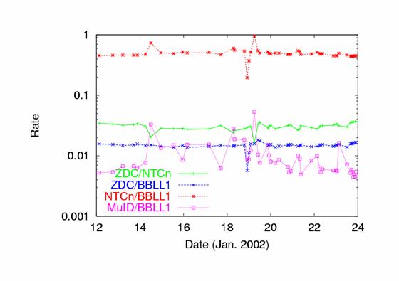
Figure 3: Time dependence of Relative Trigger
Rates
Figure 3
shows various ratios for major triggers as a function of time (date). It's
clearly shown that MuID (means 1D*MB) / BBLL1 varies significantly more than
others. This means 1D*MB rate is unstable since it was shown that BBLL1 is much
stable against beam background (shown later).
Rates of 1D
(raw) and 1D*MB were compared and they are highly (linearly) correlated. That
indicates that 1D*MB rate is dominated by non-collision related events as well
as 1D (raw).
Rate of
1D1S*MB is roughly 1/10 of 1D*MB, so we did not need any pre-scale factor for
it throughout the entire run period..
We have found
that unstable trigger rates were mostly due to the beam scraping background
with the following study done on
Ø
Cog and steer beam as usual for physics run.
Ø
Put beam collimators in the RHIC ring to scrape
beam
Ø
Miss-steer beam
Ø
Take collimators out
Ø
Put polarimeter targets in each Ring and take
them out
Ø
Put beam collimators again
Ø
Dump the beam
Figure 4: Time
dependence of trigger rates during MuID beam background study
Figure 4
shows time dependence of rates for each trigger during MuID beam background
study. And table 3 shows numbers for the first three steps.
|
Action |
BBLL1 |
NTC- narrow |
MuID1D(raw) |
MuID1D(cosmic rays subtracted) |
|
Cog and steer beam |
10.6k |
5.2k |
10.9k |
9.1k |
|
Put in beam collimator |
10.3k |
4.8k |
3.1k |
1.2k |
|
Miss-steer beam |
1.6 |
78 |
3.2k |
1.3k |
Table 3: Procedure and rates for each trigger during the
beam background study (First three steps only)
From the
first and second step, MuID1D raw rate reduced significantly. Since the rate
from cosmic rays is 1.9 kHz, it is reduced significantly from 9.0 kHz to 1.2 kHz
when cosmic rays subtracted, which gives us the upper limit of the beam gas
rate. On the contrary, BBLL1 and NTC rates remain almost same, which means
scraping beam does not affect the collision rate and just reduces the beam
scraping background which contributes to the MuID trigger rate much.
From the
second step to the third, BBLL1 and NTC rates reduced significantly, while MuID
rate remained almost same. This again tells us that most of MuID-triggered
events are not collision related. It also tells us how much beam gas or beam
scraping background contaminate
BBLL1 and NTC trigger (about 10-4 for BBLL1 and10-2
for NTC-narrow).
It is also
confirmed that the collimator works to reduce the MuID (raw) trigger rate when the
beam is blown up by a polarimeter target.
4. Trigger-Circuit Efficiency
'Trigger-Circuit (TC) Efficiency' is defined as (number of
events with both 'hardware' and 'software' trigger fires) divided by (number of
events with 'software' trigger fires). Definitions of 'hardware' and 'software'
triggers were described before.
Inefficiencies
will arise from
1.
Dead time due to delay before GL1
2.
Hardware and/or timing problem (compared to Data
FIFO) for the ROC pseudo-trigger output
We have not studied the item 2 systematically, but following
results indicates that the item 1 is the main contribution to the inefficiency.
Simple
estimation:
MuID1D raw rate varied from 3 kHz to 30 kHz (sometimes 100
kHz) according to the beam condition as described in the previous section. So
the accidental rate is
(3 ~ 30 kHz) ´1.3 micro sec = (0.4 ~ 4) % inefficiency.
Figure 5: Time (Run number) dependence of Trigger Circuit
efficiency. Statistical errors are 0.02~0.03 for 1D and 0.05~0.1 for 1D1S.
Figure 5 shows TC efficiency as a function of the Run
number. Not all of runs were shown here. Statistical errors are 0.02~0.03 for
1D and 0.05~0.1 for 1D1S. For most of runs shown here, TC efficiency is over 96%
for 1D and over 98% for 1D1S. Some fluctuations in 1D are correlated with the
trigger rate (Thus the beam background rate). These inefficiencies look
consistent with the rough estimation due to dead time above.
Since Run #39780,
cable delays had been used instead of GDGs, which made 1D-efficiency higher and
as good as 1D1S.
Figure 6: Correlation
between Trigger-Circuit efficiency and relative trigger rate (compared to
BBLL1) of MuID1D as a function of Run number.
Figure 6 shows
comparison of trigger rate of MuID1D*MB relative to that of MB = (BBLL1 OR NTC
wide) and TC efficiency as a function of Run number. MuID1D*MB rate is almost
same as the accidental rate of MuID1D (raw) and MB, and about MuID1D (raw) rate
´ 106nsec ´ 2. Then inefficiency
due to dead time of GDG is about MuID1D (raw) rate ´ 1.3 micro sec ~ MuID1D*MB
rate ´ 6.3 when
cable delay was used. For example, TC inefficiency will be 3% when the relative
rate is 0.005 and 9% when the relative rate is 0.015. This simple estimation is
consistent with results in figure 5. After Run #39780 (cable delay), efficiency
looks independent of trigger rate.
6. Muon Trigger Efficiency
Simulation shows that muon trigger efficiency is almost 100%
if muon momentum is good (above 2.5 GeV/c)
and within Muon Arm acceptance when the chamber efficiency is 100%. When the
chamber efficiency is 90%, muon trigger efficiency is estimated to be about
83%. We are now working to obtain channel-by-channel (or panel-by-panel)
chamber efficiencies from real data to get more realistic muon trigger
efficiencies.
7. Summary
Overview of
MuID Blue-Logic Trigger used for the last p+p run was presented as well as its
basic performance. Trigger rate was low enough for dimuon trigger (1D1S*MB), but
for single-muon trigger (1D*MB), we sometimes needed to introduce pre-scale
factor 4 because of unstable beam scraping background, which was shown to come
from blown-up beams. Trigger-circuit efficiency was over 96% for single-muon
and 98% for dimuon trigger. Inefficiencies are consistent with dead time in the
gate-delay generators. Muon trigger efficiency is now being studied.
8. Acknowledgement
We will thank
C-AD group, especially to Angelika Drees who has cooperated in the beam
background study.
Appendix A. Code Documentation
Codes for
trigger emulator exist for both online and offline. Online codes can be found
in online/monitoring/phnxmonitor/muid/pseudo_trig/ directory of CVS. Offline
codes are mMuiPseudoTrigger.cc and mMuiPseudoTrigger.h which are found in
offline/packages/mui/ directory of CVS. Its output, dMuiPseudoTrigger is stored
in a DST.
MLU mapping
files are found in the online directory or offline/packages/mui/wrk/ directory
in CVS. They are mui_pseudotrigmap_deep_mh1.dat and
mui_pseudotrigmap_deep_mh2.dat for Deep MLUs and mui_pseudotrigmap_shallow.dat
for Shallow MLUs. They can be created only with online codes currently. The
following shows how to:
1.
Compile codes in the online directory shown
above.
2.
Start ROOT.
3.
type “gSystem->Load(“libdesicion.so”)
4.
type “generate_mlu_data( char* output_file_name,
int last_plane, int missed_hits )” for the ‘Quadrant’ MLUs and “generate_decision_mlu_data(
char* output_file_name) for the ‘Decision’ MLU.
All file
names and their directories above are subject to be changed.