 ->e+e- at y~0
->
->e+e- at y~0
-> +- at y~2
',[Upsilon]->+- at y~2
+- at y~2
',[Upsilon]->+- at y~2
 ->
e+e-, K+K-
->
e+e-, K+K-
 , Prompt
*->e+e-
, electrons
, Prompt
*->e+e-
, electrons
 , K, p
o)/N(+ + -), d2N/d
, K, p
o)/N(+ + -), d2N/d d
, hadrons
->
e+e-, K+K-
-> +-
coincidence
, KK
d
, hadrons
->
e+e-, K+K-
-> +-
coincidence
, KK
As seen in the list of proposed measurements in Table I, the PHENIX detector must be able to measure electrons, photons, hadrons and muons, and must have particle identification capabilities to separate these different particle types from each other. For the heavy-ion program, it is also important to have a measure of the centrality of the collision on an event-by-event basis, and to measure the "signatures" over a large kinematic range. Because of this, PHENIX includs a multiplicity detector in its design and has been designed to make measurements covering a large range of rapidity and pT. For the heavy-ion program it is also necessary for the detector to be able to reconstruct tracks in a potentially very high occupancy environment (dN/dy as high as 1500). Because of this high occupancy environment, there is a potential for a large combinatorial background, making it even more important to have good particle identification to reduce background from misidentified particles combining to look like a signal of interest.
For the spin physics program the PHENIX detector will look at the spin structure of the nucleon by measuring asymmetries in the production of Drell-Yan, W, Z0, heavy quarks and direct photons.
| QGP
Signature
|
Probes
|
| Debye
Screening
|
|
|
J/->e+e- at y~0
|
electrons
|
|
J/->+- at y~2
|
muons
|
|
',[Upsilon]->+- at y~2
|
muons
|
| Chiral
Symmetry. Restoration
|
|
|
Mass, Width, Branching Ratio:
|
electrons
|
|
->
e+e-, K+K-
|
hadrons
|
| Thermal
Radiation of Hot Gas
|
|
|
Prompt , Prompt
*->e+e-
|
, electrons
|
| Deconfinement:
Phase Transition
|
|
|
<pT> spectra of , K, p
|
hadrons
|
|
N(o)/N(+ + -), d2N/dd
|
, hadrons
|
| Strangeness
and Charm Production
|
|
|
Production of K+, K-, KL0
|
hadrons
|
|
->
e+e-, K+K-
|
electrons
|
|
-> +-
|
muons
|
|
D-meson: e
coincidence
|
|
| Jet
Quenching
|
|
|
High pT jets via leading part.
|
hadrons
|
| Space-Time
Evolution
|
|
|
HBT correlations for , KK
|
hadrons
|
The PHENIX detector is shown in Figure 1 and the acceptance for the
different components is shown in Figure 2. The detector is comprised of four
separate "arms". The two Central Arms, which cover rapidity (-0.35,0.35) and
180o in the azimuthal direction will be used to detect electrons,
photons and hadrons. The two muon arms are at forward rapidities of
(-2.4,-1.2) and (1.2,2.4). In addition to these four arms there is a
Multiplicity Vertex Detector (MVD) at the very center of the detector covering
(-2.7,2.7) in rapidity which measures multiplicity (d2N/dd) on an event-by-event basis and
provides a measurement of the vertex position that is used with the rest of the
PHENIX detector for track reconstruction. In the very forward regions there
are also Cherenkov Beam-Beam (BB) counters which provide a start time for an
event, and can also give a measure of the vertex position.
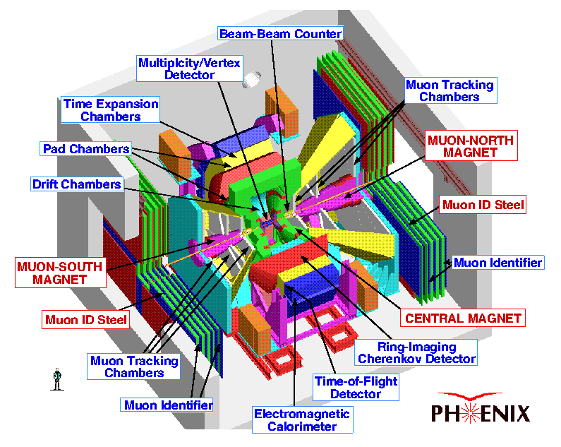
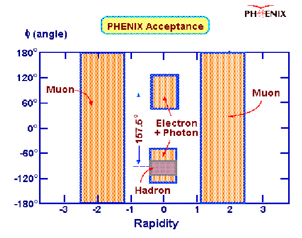
Figure 2. The rapidity and azimuthal acceptance for the electron and muon arms of the PHENIX detector. The "hadron" acceptance indicates the limited coverage of the Time of Flight (TOF) system.
The Central Arms are comprised of several sets of detectors which track charged particles and provide particle identification over various energy ranges. For momentum measurements, there is a Central Magnet (CM) which has a field in the direction of the beam pipe that falls off rapidly in r. For track reconstruction there are drift chambers, pad chambers and a Time Expansion Chamber (TEC) which provide a fine momentum measurement of charged particles and high reconstruction efficiency in central Au-Au collision events. For particle identification, there is dE/dx information available from the TEC, there is an electromagnetic calorimeter for energy measurement of photons and electrons, there is a Ring-Imaging Cherenkov Detector (RICH) for identification of electrons, and there is a Time-of-Flight (TOF) detector which is used with the momentum measurements for identification of hadrons The TOF is in a limited portion of only one of the central arms which is why the acceptance plot shows a smaller region for hadrons than for electrons and photons.
The Muon Arms are comprised of first a set of absorber materials to keep most of the hadrons that are produced at the interaction region from reaching the detection chambers. These absorber materials include 60 cm of steel from the Central Magnet as well as nosecones which are bolted to the front of the CM yoke. Following the absorber materials are two conical shaped magnets which provide a radial magnetic field over a region of approximately 4 meters in the z direction. Inside these magnets are Cathode Strip Chambers (CSCs) which are used, along with the vertex position from the MVD, to reconstruct particle momenta at the vertex. Following the muon tracking systems are Muon Identification systems which is used to trigger on muons as well as to help separate muons from punch-through pions and kaons. The muon identification system has six gaps of drift tubes with two x and two y readout planes per gap. In between each gap is a plate of steel which is 10-20 cm thick. The separation of pions from muons is achieved by requiring that muons have matching tracks in the tracking and identification systems and by comparing the depth that a particle reaches in the identification system with the momentum that is measured in the tracking system.
The simulated measurement of dN/d by the MVD for a single central Au-Au event is shown
in Figure 3 along with a comparison to the input Monte Carlo distribution. It
is expected that the measurement will be sensitive to fluctuations as small as
10% in dN/d. The
MVD will also provide a centrality trigger for PHENIX.

Figure 3. The simulated measured multiplicity of a single central Au-Au event and, for comparison, the input multiplicity.
The expected vertex resolution from the MVD is on the order of 200 m, the actual value
depending on the multiplicity of the event which will change from Au-Au running
to p-A to p-p.
Central Arms
The heavy ion measurements that the Central Arms will perform include:
1) measurement of the production of s including measurement of the branching ratio to
electrons and kaons and measurement of the mass that will be sensitive to small
shifts or changes in the intrinsic width of ->K+K-, 2)
measurement of Debye screening by looking at the production of J/ and ', 3) measurement of photons from
0.5<pT<3.0 GeV/c, 4) measurement of pT spectra from
, K, p, and 5)
potential for measuring high pT jets via leading particles
The requirements for the Central Arms are that they must be able to reconstruct
tracks in a high occupancy environment, they must be able to perform particle
identification so that different particle spectra can be collected and
background from misidentified particles minimized, and they must have a mass
resolution at the
which is sensitive to small changes in the peak position or changes in the
intrinsic width of ->K+K-.
 Figure 4. An example of the particle identification capabilities in the
Central Arms. The irreducible Dalitz background electrons are shown in
comparison to background pions and muons that are subjected to successive PID
cuts using the different Central Arm detectors.
Figure 4. An example of the particle identification capabilities in the
Central Arms. The irreducible Dalitz background electrons are shown in
comparison to background pions and muons that are subjected to successive PID
cuts using the different Central Arm detectors.
Simulations show that track reconstruction in the Central Arms is achieved with
high efficiency and small ghost track contributions at multiplicities as high
as dN/dy=1500.
An example of the particle identification capabilities in the Central Detectors
is shown in Figure 4 where the spectrum of Dalitz electrons from central Au-Au
events is shown in comparison to the spectrum of pions and muons that is
achieved as particle identification criteria are successively applied to the
pions and muons. After a requirement of a signal in the RICH, a cut on p vs.
TOF, and a cut on the shower shape in the electromagnetic calorimeter, the pion
spectrum is reduced to well below the irreducible Dalitz background. In
addition to these cuts, there will be dE/dx information available from the TEC
for particle identification.
Figure 5. The mass resolution versus pT in the Central Arms.
The mass resolution versus pT for J/-->e+e-, -->
e+e-, and --> K+K-, is shown in Figure
5. The -->
K+K resolution is very close to the intrinsic width and all
resolutions are below the 1% level.
The full mass spectrum that is expected to be obtained from the Central Arms in
approximately 8 days of running at blue-book luminosity (2x1026
cm-2s-1) is shown in Figure 6. The yields will be quite
high up to the J/
and the signal to background ratios even at the and  are on the order of 0.4, 0.2, respectively.
Muon Arms
The heavy ion measurements that the muon arms will perform include 1)
measurement of the production of -->+- which could indicate strangeness
enhancement, 2) a measurement of Debye screening by looking at the production
of J/, ', [Upsilon] -->
+-, 3)
measurement of the Drell-Yan continuum, and 4) in conjunction with the Central
Arms, a measurement of charm production may be possible by looking for
coincident e pairs
coming from DDbar-->e+-,e-+.
The requirements of the muon arm are that it be able to reconstruct tracks in a
moderate occupancy environment, that it have mass resolutions which are
adequate to separate the and  / peaks, the J/ and ' peaks and the [Upsilon] and [Upsilon]' peaks, that it
reduce the combinatorial background enough to make a measurement of the production feasible,
and that it be capable of providing a trigger for dimuon events.
/ peaks, the J/ and ' peaks and the [Upsilon] and [Upsilon]' peaks, that it
reduce the combinatorial background enough to make a measurement of the production feasible,
and that it be capable of providing a trigger for dimuon events.
Simulations have shown that in the expected occupancies of Au-Au RHIC collisions the muon arm is able to reconstruct tracks with an efficiency of 95% or better, though reconstruction of tracks at very forward rapidities is somewhat worse than reconstruction at smaller rapidities.

Figure 6. The expected mass spectrum from the Central Arms in approximately 8 days of blue-book luminosity running at RHIC.
The mass resolutions for the two muon arms are somewhat dependent on what the
final absorber materials will be (which is still under study), but are on the
order of 100 MeV for s, 130 MeV for J/s and 200 MeV for [Upsilon]s. Because the two muon
arms are not entirely symmetric, the South muon arm (which is the shorter of
the two) has a somewhat poorer resolution at high momenta compared to the North
muon arm, which effects mass resolutions of the upsilon and higher.
The muon identification system has been shown with simulations to have a trigger efficiency of 80% or higher for dimuons of interest, and achieves a pion rejection of 2.5x10⁻⁴ by combining muon identification information with the muon tracker reconstruction information, and by absorbing pions in the absorber material.
The expected mass spectrum that will be measured by the muon arm is shown in
Figure 7 where the "signal" spectrum includes all the vector meson resonances
as well as Drell-Yan and charm production and the "background" is the expected
combinatorial background which arises primarily from pions and kaons which are
produced at the vertex and decay into muons before reaching the muon absorber
material. The lower plot in Figure 7 shows the expected signal dimuon mass
spectrum after a like-sign subtraction is performed. While the
signal:background ratio at the phi mass is rather poor, the total yield in 1
year of RHIC blue-book running is expected to be on the order of 40k, so the
error in the production of s will be rather small. The yield of J/s will be on the order of 1
million/year and the yield of 's will be on the order of 23k/year. We will have
acceptance for [Upsilon]s at forward rapidity as well as central rapidity (when
one muon goes into the North arm and one muon goes into the South arm).
Summing over this entire acceptance yields on the order of 1000 [Upsilon]s/year
in the muon arms.

Figure 7. The expected opposite-sign dimuon mass spectrum from one muon arm before and after a like-sign subtraction.
Prototypes of all PHENIX detector subsystems have been completed, many of them full-size prototypes. Full-scale production will begin in many systems this calendar year. The TOF and one quarter of the electromagnetic calorimeter have been completed and installed into the detector WA98 at CERN. These will be disassembled and shipped to BNL at a later date. Data taking is expected to begin in October, 1999.
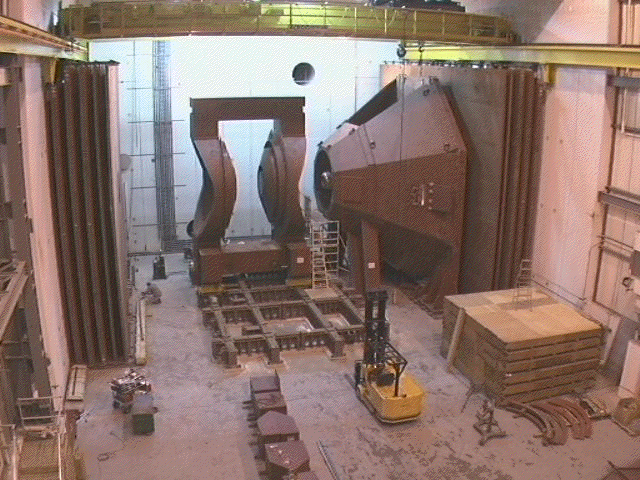
Figure 8. The status of the PHENIX detector hall as of April, 1997.