FPHX Prototype Testing Results
Back To Results Page
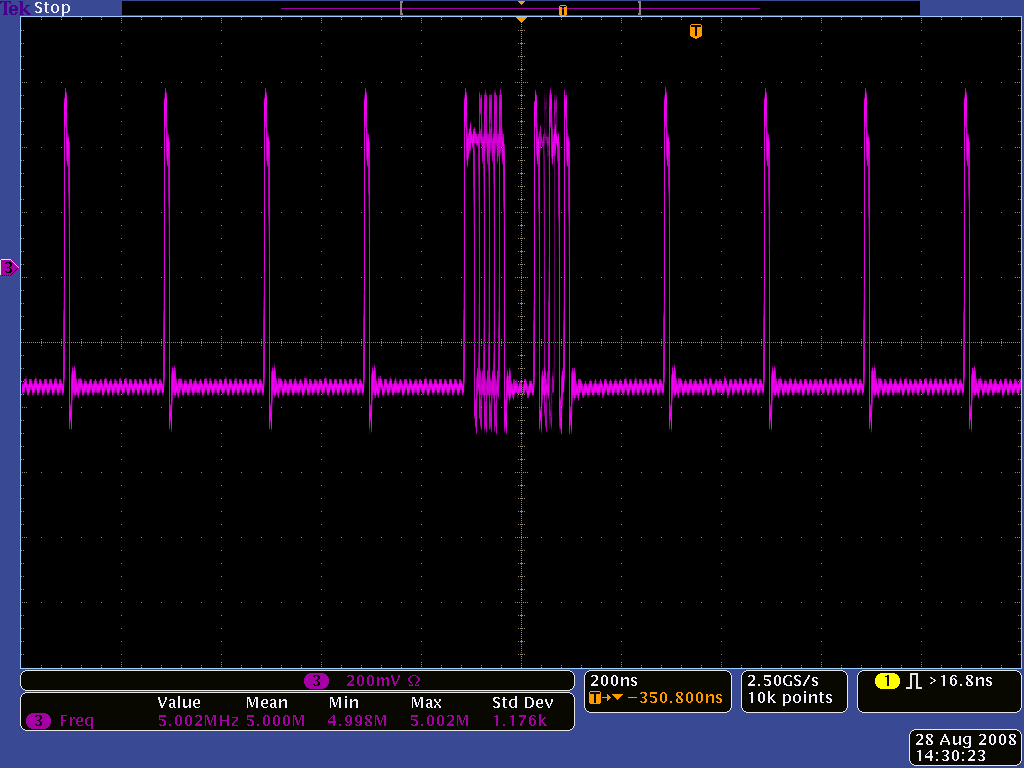
Scope capture of synch words from FPHX chip and a data word in the middle.
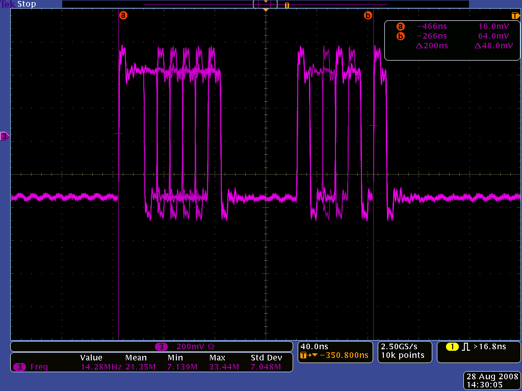
Scope capture of data words from FPHX chip with just channel 1 unmasked.
Pulser amplitude versus FPHX chip ADC value, integrated over all channels. Some known problems with
channels 0-15, two gain distributions seem to be seen.
Number of hits out of the chip versus pulser amplitude value, for one channel, when 100 pulses are sent
at each amplitude. The threshold value of the channel can clearly be seen, and the width looks reasonably narrow
(but still needs to be calibrated into electrons). Most channels give reasonable disributions like this except channels 0-15 which we assume are affected by special configurations/pads that are bonded out, and a few scattered channels in the middle of the chip.
Threshold, noise, and gain distributions for 128 channels of FPHX chip.
Threshold, noise distributions for 128 channels of FPHX chip, calibrated into electrons.
Plotting Macro (4 plots, works on chan_id, amplitude, nhits)
Plotting Macro (6 plots, works on chan_id, amplitude, adc)