Global Level-1 Operations Manual
Global Level-1 Operations Manual
March 29, 2000
J. Lajoie & S. Belikov
Iowa State University, Ames, Iowa
Overview of the Level-1 Trigger
Programming the Global Level-1 Trigger
How to create a new GL1 configuration mode
How to download a GL1 configuration mode
The Global Level-1 trigger (GL1) is the part of the PHENIX online system that is responsible for generating triggers from the Local Level-1 (LL1) reduced bit data, coordinating busies, and managing partitioned running of the PHENIX detector. The GL1 system is comprised of three types of 9U VME-P boards with very specific responsibilities:
· GL1 Board 2 (GL1-2) manages the busies and Dead-4-4 counters
· GL1 Board (GL1-3) generates the granule accept vector and manages the accepted event readout.
What To Do If You Find an Error in This Manual
As long as PHENIX is in operation, this manual will be a "work in progress." If you find portions of this manual that are misleading or inaccurate, or you have suggestions for making the manual more useful please contact the authors (lajoie@iastate.edu and belikov@bnl.gov).
Definitions
As in all manuals, a few definitions are in order to get things off on the right foot. All computer input, output, typed commands and filenames will appear in Times Roman Bold type. All program messages and references to buttons, etc., will appear in bold type. File listings are shown in Times Roman type. Computer prompts are shown as ">"; this may be different depending in the system you are logged in to.
The most critical definition, however, is reserved for the phrase "consult an expert". Simply put, and expert is someone who knows more than you. In some cases where you are asked to consult an expert you may know what to do to fix a problem, but it may be more important to find out why things went wrong in the first place.
The PHENIX Level-1 contact is:
BNL extension XXXX (Year-1 run only)
1-515-294-6952 (ISU office)
1-515-963-9818 (home - use this wisely!)
1-515-480-8312 (cell phone - use this very wisely!)
Sergei Belikov
PHENIX Counting House (7821,7815)
924-0458 (home)
A schematic of the PHENIX Trigger and Timing systems is shown in Figure 1. Note in particular the connections between GL1 and the Granule Timing Modules (GTMs), where each granule controls four signals that can be sent to GL1. Two of these are busies (FEM Unreliable and DCM Busy/Full) and are sent to GL1-2 to hold off triggers for that granule (and any partition that owns that granule). The other two (Granule Disable and Forced Accept) are available for use as reduced bit inputs on GL1-1. Note that these inputs are available by programming the LL1 mode bits in the GTM scheduler for any granule, not just LL1 participant systems.
The box labeled LL1 in Figure 1 represents any system that places reduced bit information on the GL1 backplane where it is available for trigger purposes. While in the future this will be dedicated LL1 electronics for systems such as BBC, EMCAL, etc., during the ER this functionality is provided by a transition card in the back of the GL1 crate called the Reduced Bit Input Board (RBIB). This board accepts TTL signals on Lemo cables and converts them to the LVDS standard used by the input transition cards (called the 6Rx due to its six input connectors). The configuration of the GL1 for the ER is described fully in a later section.
In order to better understand how GL1 generates a trigger, it is instructive to look at the flow of a single trigger through the GL1 system, as shown in Figure 2. The available information for making a trigger decision is placed by the 6Rx transitions cards on a backplane bus in the GL1 crate, called the reduced bit input bus. The user programs a crossbar to select which bits will be used as the input address to a SRAM lookup table (LUT). These bits can be selected as four groups of 20 (out of the 130 bits available) for each GL1-1 board in the system.
The SRAM LUT is then programmed based on the input address to generate output for selected conditions. For a given trigger, a nonzero output bit from the LUT at this point is called a raw trigger. Raw triggers are counted in VME addressable counters on GL1-1. At this point the trigger can be masked off with a user-programmable mask.
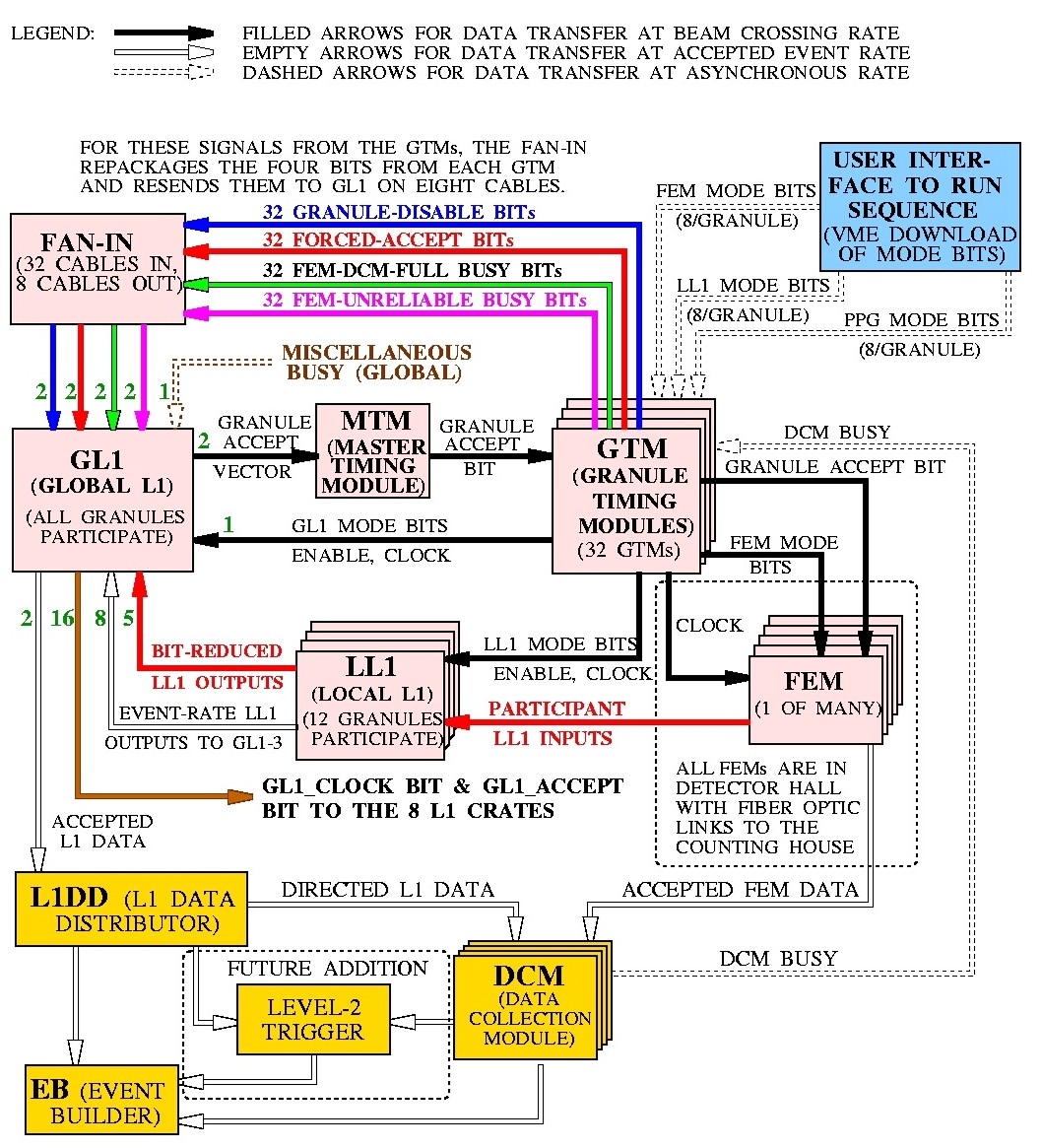
Figure 1: The PHENIX Trigger and timing system. Note in particular the four signals (Granule Disable, Forced Accept, FEM Unreliable, and DCM Busy/Full) that are available for each granule to send as inputs to GL1. The Level 1 Data Distributor does not exist for the Engineering Run; instead the GL1 accepted event data is read out directly via a DCM partitioner board.
The next step is to apply the busy for the partition that owns this trigger. The busies are contained on a second bus on the backplane, called the partition busy bus, that is managed by GL1-2 and includes the Dead-4-4 counters. A programmable crossbar maps the partition busy for the partition that owns the trigger in question and the busy is applied to the raw trigger. A trigger that passes the busy test is called a live trigger and is again kept track of by counters in GL1-1.
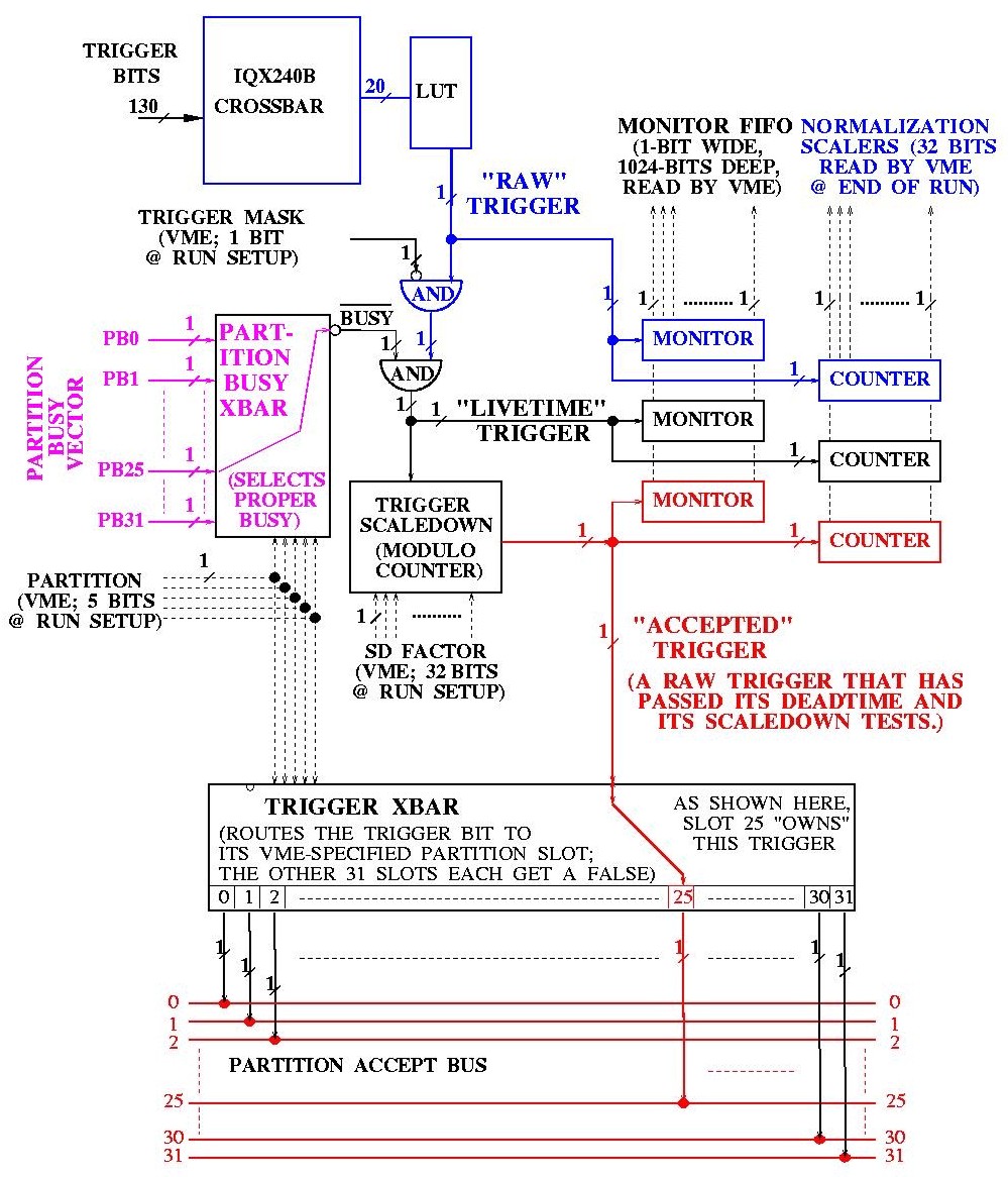
Figure 2: A closeup of a single GL1 trigger, showing the flow and programmable elements in the system.
Finally, a programmable scaledown counter is applied to prescale active triggers, and again the output is counted. A trigger passing the scaledown test is called an accepted or scaled trigger and is mapped by a third crossbar to a line on the partition accept bus. This bus is monitored by GL1-3 and used to generate the granule accept vector (via another crossbar, not shown in Figure 2) that is sent to the Master Timing Module (MTM).
From the point at which reduced bit data is presented on the reduced bit input bus to when the granule accept vector is sent to the MTM requires three beam clocks in GL1.
The GL1 trigger crate is located in PRR.1.1 in the electronics area of the PHENIX counting house. The Timing System is located in rack PRR.1.5. The Level-1 trigger rack is typically left closed to prevent dust and contamination from building up on the GL1 boards. If you need to open the rack you will need a "crate key".
For reference, Figure 3 shows a schematic diagram of the GL1 crate and
associated 9U VME cards, transition cards and beam rate inputs. This diagram
can be used to identify the GL1 transition cards and GL1 internal cabling.
It should be noted that each end of the GL1 LVDS cabling is labeled with
the signal names on each connector end.
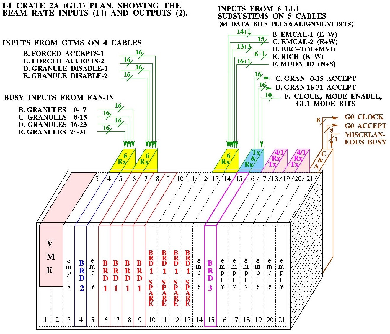
Figure 3: A schematic view of the GL1 crate, showing the associated transition cards and beam rate inputs. Each line in the above corresponds to an LVDS cable. Note that for the ER GL1 uses a shorter backplane and the 9U and transition cards may not be located exactly as shown.
Like all VME systems in PHENIX, the GL1 crate is controlled by a PPC VME processor (currently iocondev14). This processor is located in the leftmost slot (slot 0) of the GL1 crate and can be reset by pressing the Reset button on the front panel. Note that all the GL1 boards monitor the VME SYSRESET signal and will automatically reset themselves when the VME processor is reset. Thus, resetting the processor will necessitate reloading the GL1 configuration to ensure proper trigger operation. While each of the GL1 boards have independent reset buttons, use of these buttons is strongly discouraged. Should it be necessary, the proper way to reset the GL1 crate is reset the PPC VME processor by pressing "Reset" button on the PPC front panel.
Figure 4. The GL1 board front panels and a description of their LEDs. The busies indicated by GL1-2 and GL1-2 are likely to be of particular importance to the user.
The GL1 trigger boards contain a set of lights intended to indicate to the user quickly the status of the various GL1 signals, as shown in Figure 4. Of particular importance are the Granule Busy and FEM Unreliable lights on GL1-2. If either of these lights are illuminated for a given granule, triggers for that granule (and any partition that contains it) will be busied out. This is often the first place to look when the complaint "Hey, I'm not getting any triggers!" arises. In addition, the global VME busy on GL1-2 is indicated by a small LED in the lower left of the board.
The GL1-3 board contains a set of "global" busies that will hold off all triggers in all partitions, as indicated by red lights on the front panel. The Misc/Global busy is (at present) connected to the DCM that is receiving the GL1 accepted event data. The Governor Busy is a busy generated by a programmable "throttle" on the GL1 accepted event rate; currently this throttle is set to limit the accepted event rate to less than 25kHz.
In addition to the busy lights on GL1-3, there is also a green LED to indicate that the GL1 system is receiving a proper beam clock signal from the GTM in the GL1 crate. This light should always be lit during normal operation of the trigger - without a beam clock, most elements of the trigger will not function. When the GTM controlling GL1 is properly cycling (the Mode Enable signal is high) an additional green LED will be lit on the GL1-3 front panel. While this LED should be on for normal operation of the trigger, it should be off before or during configuration of the GL1 system. Certain items, such as the GL1-1 LUTs, will not permit load operations while Mode Enable is high.
Finally, all three boards have a green LED to indicate VME activity. This light can be used as a visual indication to verify that software is actually addressing the correct boards during program operations such as configuration, etc. A red LED at the top of each board indicates failure of the Geographical Address Parity circuit - this LED should never be lit during normal operation. If this LED is lit, it likely indicates a catastrophic failure in the GL1 board or the VME crate - call an expert.
Please note that the GTM controlling the GL1 is not located in the Timing System rack, but in the crate with the GL1 itself. This simplifies the control of GL1 and facilitates software control of the GL1 GTM for downloading and configuration. While the normal GTM tools can be used to configure this GTM and load mode bit files, the GL1 configuration utility takes care of this automatically for ordinary running. In addition, starting and stopping the GL1 GTM is done automatically when using the GL1 configuration utilities.
Much of the cabling that is critical to the proper operation of GL1 is located in the back of the Timing and Control System rack (PRR.1.5). In the bottom of this rack there is an aluminum box labeled GTM->GL1 Transition box which receives 32 RJ45 cables (one from each potential GTM) and maps them to the eight LVDS cables that are sent to GL1. Each RJ45 connector on the transition box corresponds to a very specific granule and labels on the box will show you how to identify the connectors. It is where the RJ45 cable is plugged into the transition box that defines what granule number a given GTM is mapped to. It is important to keep this hardware mapping synchronized with the software described in later sections or mass confusion will result!
In addition, two cables carry the granule accept vector from the Standard Transition card in the GL1 crate (see Figure 3) to the MTM fanout in the back of the Timing and Control rack. This MTM fanout card receives the two LVDS cables from GL1 and splits them out into 32 RJ45 connectors to the GTMs. The MTM card has two RJ45 blocks; the upper block contains granules 0-15, while the lower contains granules 16-31. Each block's connectors are numbered "like a chip" starting in the upper left hand corner, down the lefthand side, and up the righthand side of the connector.
Once again, the RJ45 cabling is crucial - a given GTM must be connected to the same granule number in both the GTM-> GL1 fanout box and the MTM fanout box. If this is not followed, a given GTM will either not receive accepts (at best) or receive accepts for a different granule (at worst).
The above descriptions of the GL1 and Timing and Control cabling lead to one simple rule - please leave it alone! If you need to swap out a GTM (for whatever reason) leave the cabling and transition card in the back of the crate alone and just swap GTMs in the front of the crate. If you must remove and replace a GTM transition card, double (and triple) check that the GL1 and MTM cabling is correct when you are finished.
Programming the Global Level-1 trigger consists of five separate steps, that are combined in one GUI:
This section will take you through each of the five steps in detail. After reading this section you should be able to completely reconfigure the GL1 trigger to suit a wide variety of conditions.
Before we start, let's set some ground rules. The instructions that follow assume that you have logged into phoncs0 as user phoncs, and executed the setup command files for both the production release of the online distribution and the GL1 package. There are two reasons for this:
> setuponcs R-pro
selecting release R-pro
-------------------------------------------------------------------------
setting up the ONCS environment R-pro
-------------------------------------------------------------------------
> cd $GL1_MAIN/config
The above example will leave you in the directory /export/software/oncs/R-pro/online_distribution/GL1/config. This directory contains the GL1 configuration programs and scripts.
To start GL1 configuration GUI type: GL1cfgC - stands for GL1 configuration for CORBA version. You will see the next window:
Figure 5. GL1cfgC GUI window as it appears at the very beginning.
As you can see all buttons (except EXIT) are disabled. To activate them choose a name for a GL1 mode. You can type a new name in the upper small self-expanded window or choose a name of already existed mode from the list box below. Figure 6 shows how GUI will look like after you have chosen the mode.
Figure 6. GL1 GUI window after mode modeF_All was chosen by user.
The name of GL1 mode is actually the name of the subdirectory located at $GL1_DATA (the same as $ONLINE_CONFIGURATION/GL1/) area. Each such subdirectory keeps 16 configuration files but you need know nothing about them - program will create and modify them itself.
In this document we use modeF_All configuration as an example. This mode has 32 partitions, each partition has one granule and one trigger. For simplicity partition number is the same as its granule and trigger number (1-to-1). Only Forced Accepts are used to configure triggers: forced accept of a granule N fires trigger number N that belongs to the partition N.
We will start by associating granules with partitions. Press the button "Granules->Partitions". You should be rewarded with a screen like that in Figure 7. This is a simple mapping program, with partition names (or numbers) listed in columns and granule names (or numbers) listed in rows. You assign a granule to a partition by clicking the mouse on the box corresponding to the granule and partition number intersection. If you select a granule incorrectly, you may deselect it by clicking again on the highlighted box or by clicking on correct position (since granule can belong to only one partition the previous selection will be deselected). A message will appear under the command buttons confirming the mapping and unmapping actions.

Figure 7: The granule to partition mapping configuration window. Mode modeF_All mapping is shown.
At this point a few important comments are in order. First of all, the granule names and their assignment to granule numbers are contained in the file .gl1_granule_names in the $GL1_MAIN/config directory (note that this may be a symbolic link to a file in the online configuration directory). The format is very simple - granule number is listed followed by a name. An example is listed below:
You can change a partition name: click the corresponding name in the Partition Names row and just edit its name in the entry above. If you move mouse over partition box you will see its name in the entry. On fig. 7 the name of partition 6 is displayed.
When you hit Save&Compile button all 32 partition names will be saved into the file named partition.names located in current mode subdirectory. These names will be used later by Partition Server and by Run Control to describe partitions of current GL1 configuration.
OK, so you are happily clicking away and you have a granule to partition map that you like. (Note that the program will prevent you from mapping a granule to more than one partition - a definite PHENIX no-no!) Selecting the Save&Compile button at the top of the grid will allow you to save your configuration file and to create crossbar files that can be downloaded into the GL1 boards. If you receive any message other than Crossbar files compiled successfully across the top of the screen, consult an expert. If all is well, you can exit the program with the Quit button.
You can load Granules->Partitions mapping from other GL1 mode by pressing Load button. You must click Save&Compile button to create corresponding configuration files in your mode configuration!
Pay attention to "GL1 Configuration" window: before you started granules mapping the "Granules->Partitions"button was gray; when you made any changes to the mapping the button becomes red; when you saved & compiled your mapping the button becomes green. This is the policy for all buttons of "Granules->Partitions" window, it indicates the status of each operation.
The next step is to assign triggers to partitions.
Clicking button "Trig->Par" of any GL1-1 button group will produce
the configuration screen shown in Figure 8.
Figure 8: The trigger to partition mapping program. The interface is similar to that used for the granule to partition mapping program. Configuration for modeF_All is shown.
Since the interface for this program is almost identical to the "Granules->Partitions" we have previously discussed, we won?t go over it in great detail here. Some of the same caveats for mapping granules to partitions apply for mapping triggers to partitions, however. Note that a given trigger can belong to one and only one partition, and the program will prevent mapping a trigger to more than one partition.
The next step is to define the address to the LUTs that will be used to define each trigger by mapping lines from the reduced bit input bus; you will have to do this for each trigger you mapped to a partition in the previous step. Start the configuration program by pressing "Bits->LUT" button. You should see a configuration screen like that shown in Figure 9.
Figure 9: The GL1 lookup table address mapping program. The LUT to be configured is selected by the radio buttons at the left, while the address bit to be mapped is selected by the radio buttons for each bit. Clicking on a named signal will map that signal to the input bit. ModeF_All configuration for LUT 0 is shown as an example.
It is useful to remember the architecture of GL1-1 at this point. Each set of four triggers is generated as the output of a LUT that takes 20 bits of address from the GL1 reduced bit input bus. Your job at this point is to define which 20 bits will be mapped to which lookup table. Triggers 1-4 are controlled by LUT 1, 5-8 by LUT 2, etc. Select the LUT you want to work with by the radio buttons at the left of the configuration screen, then select the GL1 reduced bit input bus elements from the any of 4 list boxes at the right. As you can see some signals of "Forced Accept" and "Disable Granule" have names that correspond to granule name. If you want to clear some bit assignment first click this bit then click <none> string in "Other" list box. Start from the lowest bits in the address. When you "connect" the selected bit the next bit will be automatically selected, so just click bit names one by one. Don't worry about uncommitted address bits; the program will automatically force those bits low when the crossbar files will be compiled.
Note: try always to start from Bit 0 and do not skip bits - it will significantly reduce LUT creation time.
When you have fulfilled all necessary connections press button "Save&Compile". Program will save your Bits->LUT configuration, create and compile some crossbar files, and write for you a skeleton for raw triggers firing logic.
Up to this point, configuring the GL1 has been a purely graphical exercise. What follows next may sound complicated, but keep in mind the basic job of this utility is to loop over all combinations on the 20 bit LUT address and generate raw triggers for only those combinations that you select.
To start with, click "Trig Logic" button - it should open the skeleton of logic file in an emacs window, and the file it contains should look something like this:
LUT 0 {#define ForcedAccept0_bit0 0x1#define ForcedAccept1_bit1 0x2#define FA_BBC_bit2 0x4
#define FA_ZDC_bit3 0x8
#define Others 0xffff0
TRIG 0 {
Others.eq.0
}
TRIG 1 {
Others.eq.0
}
TRIG 2 {
Others.eq.0
}
TRIG 3 {
Others.eq.0
}
}
LUT 1 {
#define FA_MVD_bit0 0x1
#define FA_DC_W_bit1 0x2
#define FA_PC_W_bit2 0x4
#define FA_TEC_W_bit3 0x8
#define Others 0xffff0
TRIG 4 {
Others.eq.0
}
?
(The listing should include all 8 LUTs and all 32 triggers as separate sections, but I have truncated the list here to save space.) As you can see, the LUT input file contains sections that start with a LUT name (LUT 0) and are surrounded with braces {}. Inside LUT section Bit->LUT program defines named masks on the bits connected to this LUT address and one mask "Others" for each LUT that defines all disconnected bits. Names of the masks are the same as in Bit->LUT list boxes except additional suffix _bitX is added where X indicates to what bit is this signal connected. This is done just to remind you Bit->LUT configuration and to avoid ambiguity in case when you connect the same signal to more then one input bit.
You may be already have noticed that in addition to mask definitions inside each LUT section there are four TRIG sections also surrounded with braces {}. This is up to you to determine logic that will fire each trigger.
Fill in the TRIG section with tests based on these masks to define trigger conditions. The comparisons in the TRIG section recognize the keywords ".GT." (greater than), ".LT." (less than), ".EQ." (equals), ".GE." (greater than or equal to) and ".LT." (less than or equal to). Program is case insensitive to comparison keywords, so you can write .gt. as well as .GT. But program is case sensitive to mask names, so be careful while typing them (better just use Copy and Paste).
All lines in TRIG section are combined by logical AND, so for example
TRIG 2 { FA_BBC_bit2.gt.0 Others.EQ.0 }means: fire trigger 2 when Forced Accept from granule BBC is high AND disconnected entries (mask Others) are low.
The following is a fragment of logic file for modeF_All configuration.
LUT 0 {
#define ForcedAccept0_bit0 0x1
#define ForcedAccept1_bit1 0x2
#define FA_BBC_bit2 0x4
#define FA_ZDC_bit3 0x8
#define Others 0xffff0
TRIG 0 {
ForcedAccept0_bit0.gt.0
Others.EQ.0
}
TRIG 1 {
ForcedAccept1_bit1.gt.0
Others.EQ.0
}
TRIG 2 {
FA_BBC_bit2.gt.0
Others.EQ.0
}
TRIG 3 {
FA_ZDC_bit3.gt.0
Others.EQ.0
}
}
LUT 1 {
#define FA_MVD_bit0 0x1
#define FA_DC_W_bit1 0x2
#define FA_PC_W_bit2 0x4
#define FA_TEC_W_bit3 0x8
#define Others 0xffff0
TRIG 4 {
FA_MVD_bit0.gt.0
Others.EQ.0
}
?
You can define your own mask if you wish. For example, suppose you want to fire trigger 0 if any of 4 LUT input bits has signal. You can add to mask definitions:
LUT 0 {#define ForcedAccept0_bit0 0x1#define ForcedAccept1_bit1 0x2
#define FA_BBC_bit2 0x4
#define FA_ZDC_bit3 0x8
#define Others 0xffff0
#define Any_of_4 0xf
and define trigger 0 logic as:
TRIG 0 { Any_of_4.gt.0 Others.EQ.0 }
Thus by combining mask bits and by adding new lines in trigger section you can create sophisticated logic for trigger firing.
You will definitely say: "Hey, guys! Your code is half C-like half Fortran-like! Can it be only in one language?" Calm down, it will be completely C-like later.
OK, you modified the trigger logic skeleton file as you desired. What?s next? First, save file just by choosing "Save Buffer" from File menu of emacs. Then exit emacs. Note: you can?t continue to use GL1cfgC program until you close this emacs session. You will see that "Trig Logic" button becomes green while "Create LUT" is now red. Push this red button and wait while program create a Look Up Table. If program finds any error in your logic file it will stop compilation and will write error message in GL1cfgC message window. The text color will be red. If no errors are found the program will create and write down the LUT. The size of LUT file is 1M strings, so it will take some time to do it. If everything is OK program will type "Done!" in message window and will convert the color of "Create LUT" button to green.
Now the last button of GL1 configuration GUI: "Scaledown". It permits you to define scale down factor for each trigger. We definitely will not use it in Year-1 run, so just keep all values equal to 0.
Fig. 10. This window will pop up when you hit "Scaledown" button. You can set a scale down factor for each trigger of this GL1-1 board.
Congratulations! You configured GL1 for one GL1-1 board.
It is important to note that for the Year-1 run there is only one GL1-1 board. When there are multiple GL1-1 boards in the near future, you will have to repeat the previous four steps (Trig->Par, Bit->LUT, Trig Logic, Create LUT) for each GL1-1 board in the system.
Generally program defines the number of GL1-1 board itself reading file .GL1temlate in $GL1_DATA area. This file is template for GL1.config file that is created by GL1cfgC in each mode subdirectory. Only experts have right to update this file. Nevertheless you can change the number of GL1-1 boards yourself by typing the desired number into the entry labeled "Number of GL1-1 Boards". If you increase the number of boards additional blocks of GL1-1 buttons will appear, if you decrease this number the rightmost blocks will disappear. Program will make itself the corresponding changes to GL1.config file.
Button "Save&Compile All" will save and compile Granules->Partitions and Trig->Par, Bit->LUT configurations for each GL1-1 if any of them was changed, but you must make steps Trig Logic and Create LUT yourself for each GL1-1.
If you have reached this point after working through all of the above configuration steps, congratulations! You now have a complete GL1 configuration and you are ready to try it out by downloading it into the GL1 system.
The GL1 system is most easily controlled by the average user though a Java gui. This gui encapsulates the most common GL1 functions into a set of easy to follow menus and button.
To start the gui, change directory to the GL1 area and do the following:
Note: If instead of GUI you see on your terminal the message
"Exception during ResolveName
Object - gl1. - not found."
then just reset the GL1 PPC controller.
If you are having a problem with GL1 and you suspect that a board
is dead or not answering, you can scan the current crate configuration
with the Scan crate button. This will pop up a window showing you
the configuration of GL1 boards found in the crate, along with any transition
cards.
Figure 11: The GL1 gui crate configuration window.
Commands are accessed using the buttons under the Options heading or by
the menu headings in the upper left. Configuration pages for different
elements can be accessed using the buttons directly above the PHENIX logo.
In order to download the current configuration that you defined in the previous section select the "Run Config. Script" button. You will be presented with a file box that you can use to select the GL1.config file from the directory of your configuration. At this point the gui will parse the configuration file and download the GL1 components - if you watch the VME access lights on the boards, you will see multiple accesses for each board. Configuration Progress bar will show you the downloading progress. If any error occur during the downloading the message window with problem explanation will appear on the screen.
If "Configuration Progress" bar has reached 100% without any error message - congratulations, your GL1 mode has been successfully downloaded!
Note that running a crate configuration script automatically sets the global VME busy, and the VME Busy checkbox should be red after the script is complete. In order to clear the busy, click the "Clear VME Busy" button on the GL1 gui (right bottom corner). The trigger will now be fully enabled, and should now provide triggers and accepts (for those partitions that are not themselves busy, of course).
The GL1-1, GL1-2 and GL1-3 pages in the configuration gui contain additional commands that allow you to read out and reset the GL1 counters. Note that counter readout windows are updated automatically by a background task - if you want to monitor the GL1 counters you can set the counter window in a corner of our screen and it will update automatically, approximately every second.
The GL1-1, GL1-2, GL1-3 and BBC functions will be more fully described as this document is expanded. For now, feel free to explore. Of particular use are the "Clear counters" function on the GL1-1 page (which clears the raw, live and scaled trigger counters for the board) and the "Clear Gran. Counters" function (which allows you to clear selected granule accept counters in GL1-3).
We will describe later in the chapter for advanced
user how to use all these and other buttons. For an ordinary person on
shift you already know enough to create and download GL1 configuration
mode. Good luck!