
Figure 1. RHIC is an accelerator being built to study high-energy hadronic collisions. The main program collides counter-circulating heavy ion beams at 100 GeV/nucleon in a search for a state of matter in which quarkis and gluons are deconfined (the Quark-Gluon Plasma, or QGP). Different species and energies are available to allow systematic studies of the hot, dense matter that is created. High energy proton beams can also be accelerated with a finite spin polarization to allow studies of the spin structure of nucleons.
Figure 2. PHENIX is one of the large experiments situated at the accelerator crossing points (places where the beams can be made to collide). The goal of the experiment is to measure as many possible signatures of the deconfinement phase transition as possible as functions of the violence of the collision. This figure shows an artist's rendition of the experiment in a cut-away view to show the inner detectors. The two muon are shown at the far left and right-hand sides of the figure. The muon arms consist of two distinct detectors, the Muon tracker which consists of three cathode-strip chambers inside of the octagonal Muon magnet, and the Muon identifier which consists of layers of Iarocci tubes interleaved between steel plates.
Figure 3. This figure shows a real photo (with real physicists for scale) of the Major Facility Hall.
Figure 4. One of the key measurements for the Muon arms is the suppression of quarkonia states predicted to occur during the deconfinement phase transition. This measurement requires accurate determination of the production cross-sections for the J/Psi, Psi' and Upsilon mesons. (The different states have different radii, leading to different amounts of suppression - measuring this differential suppression is key). There are also important measurements to be made with the phi meson (mass-shifts and width variations are predictions for QGP formation) and with single muons (enhanced charm production is a prediction for QGP formation; these measurements are also important for the spin program).
Figure 5. In order to carry out the muon physics program, excellent momentum resolution is needed as is significant pion rejection and triggering capability. To achieve these goals the muon spectrometer has two distinct detectors. The Muon Tracker makes an excellent momentum resolution measurement
Figure 6. This picture shows a short (4") Iarocci tube. HV, signals and ground are connected through pins in the orange endcaps. The black "comb" is the cathode. The anode wires (probably not visible) are strung parallel to the comb, centered between the tines of the cathode comb. The tube capacitance is 100pF/m; a total of 250-500 pF for our 2.5-5 m tubes. We read passively OR two tubes into one readout channel, making the capacitance 500-1000 pF/channel.
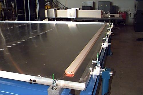
Figure 7. Full-scale MuID prototype panel at ORNL, shown in its horizontal (assembly) position. The tubes shown are mounted to the panel midplane. The panel is flipped so that the other side of the midplane is exposed (and the tubes shown are on the bottom side) and a series of tubes are mounted in the orthogonal direction. Note that the tubes are stacked in two planes for each orientation. The planes are staggered by half a cell (0.5 cm) to avoid inefficiency around the cathode comb and the long drift times associated with hits in the cell corners.
Figure 8. This picture shows a beam's eye view of a single Muon identifier sensitive layer (gap). The fine grid shows a line for every other Iarocci tube. The large panel edges are shown in red; the small panel edges are shown in sky blue.
Figure 9. Since the decision was made not to pack the front-end electronics inside the detector, mechanical constraints were greatly reduced. Cables can take the signals where we need them - between the west edge of the MuID steel and the wall of the major facility hall. We do have some electronic constraints as sumamrized above.
Figure 10. Block diagram of the data flow for a single channel. The blocks inside the dotted box can be combined into a single ASIC.
Figure 11. This summarizes the channel counts for MuID FEE.
Figure 12. This is a very rough layout of the FEM Crate and its components.