Response Chain
The purpose of the response chain is to generate simulated raw data, in the form of DCM packets, from the GEANT "hits" data.
This chain can be broken up into two pieces: one subchain that transforms PISA hits into MuID raw hits, and another that constructs DCM packets from the MuID raw hits and writes the packets to a PRDF stream. This division is occasionally useful practically, since the MuID raw hit data can, if desired, be used directly in the reconstruction chain without writing a PRDF file.
The transformation of PISA hits to raw hits includes the following effects:
Determination of which two-packs were hit. The current GEANT simulation in PISA models a MuID gap as a single plane, rather than as a collection of tubes, so that a GEANT hit consists of an arm, gap, position vector, momentum vector, particle id, and a GEANT track id. This step, therefore, determines which two-packs in the arm and gap lie "close" to the position of the GEANT hit.
In the future, this functionality is expected to become part of the MuID GEANT simulation itself. That is, the GEANT model of the MuID detectors will be a collection of tubes, so that the GEANT hit information will include the specific tubes that were hit.
Inefficiencies of the two-packs. This effect is modeled simply as the probability that a given two-pack will have a raw hit, given that there was a GEANT hit in that two-pack.
Random noise sources. This effect is modeled as an additional number of random hits in each gap per event. The number of additional hits is assumed to be distributed as a Gaussian, with mean and sigma parameters that can be set at run time.
Cross-talk between two-packs. To be added.
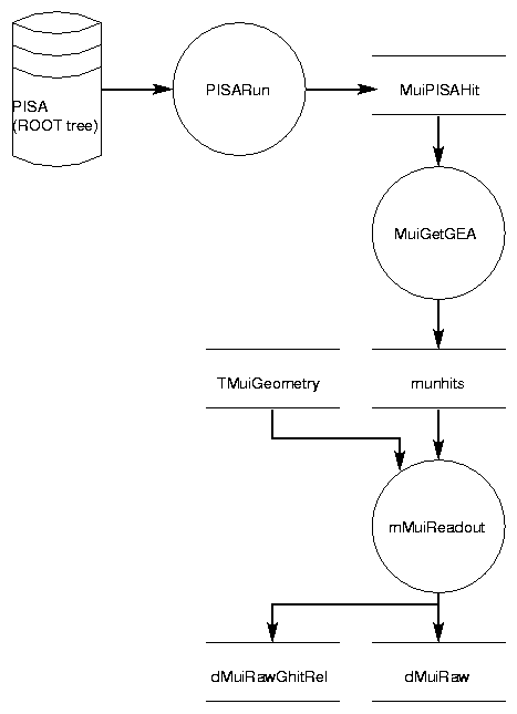
The identities of the GEANT hits that produced each raw hit are stored in a dMuiRawGhitRel relational table.
Figure 2. Objects involved in creating fake raw data from PISA hits.
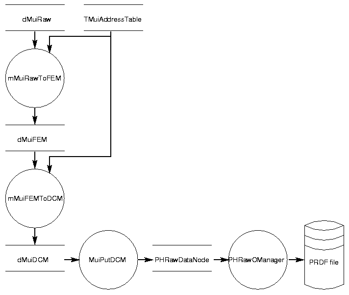
The rest of the response chain is involved with the task of creating the DCM packets for MuID. The mMuiRawToFEM module determines the "hardware" address (indexed by FEM, ROC, cable, and channel) of the entries in the dMuiRaw table, and generates the bit patterns (stored as 16-bit words) corresponding to the hardware addresses. Then the mMuiFEMToDCM module appends an additional 16 bits to each data word to identify the source of the data (readout card and word numbers), and adds the DCM header and trailer words.
Figure 3. Objects involved in creating a DCM packet and writing a PRDF file.