Reconstruction Chain
The purpose of the MuID reconstruction chain is to find roads, collections of hit two-packs that are likely to have been produced by a single particle traversing the muon identifier. These roads are then used to "seed" the muon-tracker (MuTr) software, which then finds muon-arm tracks. Once the tracks have been found, the software identifies the type of particle that produced each track.
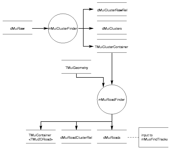
Figure 5. Objects involved in reconstructing raw data.
Finding Clusters
We begin by finding clusters, groups of contiguous (or nearly contiguous) two-packs of the same orientation in a single panel which all register signals in the event. (Because we cannot know a priori which horizontal and vertical hits were produced by the same particle, we wait until the road-finding procedure to combine the horizontal and vertical hits.) This is done to provide convenient two-dimensional (X-Z or Y-Z) space points for the road finder.
The input to the cluster finder is a TMuiHitContainer object. The clusters found are stored in a TMuiClusterContainer object (and copied to a dMuiClusters table; the identities of the raw hits stored in each cluster is copied to a dMuiClusterRawRel table.)
There are two parameters (per gap) that control the cluster finder:
the cluster gap, the maximum number of contiguous non-firing two-packs allowed to be contained within the boundaries of a cluster. (A cluster may potentially contain more than one set of contiguous non-firing two-packs.) A cluster gap of zero requires that the cluster contain a contiguous set of firing two-packs, while nonzero cluster gaps allow larger clusters with missing two-packs.
the maximum number of firing two-packs that a cluster is allowed to contain. Setting this parameter to 1 effectively turns off the clustering, which is the current default behavior.
Finding Roads
Preliminary docs for the parametrized road finder are found in the summary of the 1999 MuID reconstruction workshop. In a nutshell, the software starts with a road seed, which is constructed out of clusters found in one or two of the seed gaps, and then finds additional clusters that are consistent with a two-dimensional (X-Z or Y-Z) road trajectory; a cluster that is "close enough" to the projection of the road to the gap containing that cluster is generally accepted. The projection of the road is steered, and the size of the cluster search window is adjusted, to allow for deviations from a straight-line trajectory due to scattering in the steel placed between the gaps. Once all gaps have been checked for acceptable clusters, we have a "1D" (X-Z or Y-Z) road. Some of these roads are then eliminated based on the number of skipped gaps in the road (i.e., gaps with no clusters attached), the total number of gaps contributing clusters to the road, et cetera. The software then attempts to construct "2D" roads from pairs of "1D" roads, based on requirements such as the consistency between the number of hits (total and gap by gap) in the two "1D" roads, consistency between the last gap with attached clusters, et cetera. The combined roads are then available to be used in later stages of the reconstruction.
The behavior in detail of the algorithm is controlled by the settings of several parameters, which are stored in the dMuiRoadControl table.
The input to the road finder is a TMuiClusterContainer object, containing the clusters found by the cluster finder. The X-Z and Y-Z roads found by the road finder are stored in TMuiContainer<TMui1DRoad> objects, and the combined "2D" roads are stored in a TMuiContainer<TMui2DRoad> object. The road data are also copied to a dMuiRoads table; the identity of each cluster in each road is copied to a dMuiRoadClusterRel table.)
Identifying Particles
(Docs for the next-generation particle identifier will be added once it becomes the standard ...)
Particle identification for the muon arms is performed by the mMuiMuonId module; the software attempts to identify each track as "a muon" or "something else." The input to mMuiMuonId consists of the muon tracks found by the muon-tracker (MuTr) software; the track parameters are stored in the dMuoTracks table. Each track is made up of both MuID and MuTr clusters, and thus represents the trajectory of a particle through the entire muon arm, including a reconstructed momentum vector. The mMuiMuonId module uses the momentum information and the hit patterns in the MuID detectors to determine the probability that the track was produced by a muon.
The output of mMuiMuonId is stored in the dMuoTrackRoadRel table, which contains, for each track, the track index from the dMuoTracks table, the road index from the dMuiRoads table, a "quality factor" measuring the goodness of the road-track match, and the muon probability for the track.
A simple algorithm for determining the muon probability is currently used: given the last gap in the MuID that the track reached, the track is a muon (100% probability) if and only if the magnitude of its momentum does not exceed some cut-off value. The cut-off parameters are specified at run time in the dMuiMuonIdProfilePar table. (The track's trajectory must also project back to (0,0,0) within some window, also specified in dMuiMuonIdProfilePar.)
Diagnostic Histograms for Reconstruction
To provide some simple measures of the performance of the reconstruction software, various histograms are created and filled. This task is performed by the mMuiHistoBase module, using the PHENIX histogram factory software.
The inputs to the mMuiHistoBase are the tables used in the reconstruction: dMuiRaw, dMuiClusters, and dMuiRoads, and the corresponding relational tables: dMuiClusterRawRel, dMuiRoadClusterRel, and dMuiRoadRawRel. No simulated data is used in making these histograms. The following quantities are calculated and histogrammed (the name of each histogram is in parentheses):
(hHitCount) number of two-packs hit per event
(hClusterCount) number of clusters found per event
(hG3RoadCount) number of roads found reaching at least the fourth gap per event
(hG4RoadCount) number of roads found reaching the fifth (last) gap per event
(hAllRoadCount) total number of roads found per event
(hClusterSize) size of a cluster. This is calculated as the total number of two-packs inside the cluster boundaries (including the two on each end).
(hClusterMissing) number of "missing" (not hit) two-packs inside a cluster. This is the cluster size described above minus the total number of struck two-packs in the cluster.
(hLastPlane) the last gap (0-4) reached by a road
(hTotalHits) the total number of struck two-packs contained within a road
(hMaxHits) the maximum transverse size of a road, measured as the number of struck two-packs attached to the road in the gap where this number is a maximum for that road
(hRoadVertexXY and hRoadVertexZ) the (X,Y,Z) position of the projection of the road trajectory to the event vertex
The histograms are saved to a file "Mui.root".