postscript version
Last modified 15 Nov 98 HvH
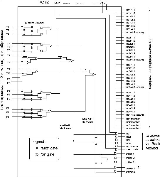
The board shown below is a 6U single-width VME board. It does not 'speak VME' however, it only gets 5V from the crate's backplane. Inputs are the signals from the sensors (on the left), as well as from the computer, via digital I/O lines (on the top). Output (on the right) are control signals that can turn off selected LV modules. Some protection against bad sensors is provided by the '2 out of 3' logic on the left. This board is currently being built as a wire-wrap.
Not shown:
