MVD Cooling Schematic
Last update: 14 Nov 98 - HvH
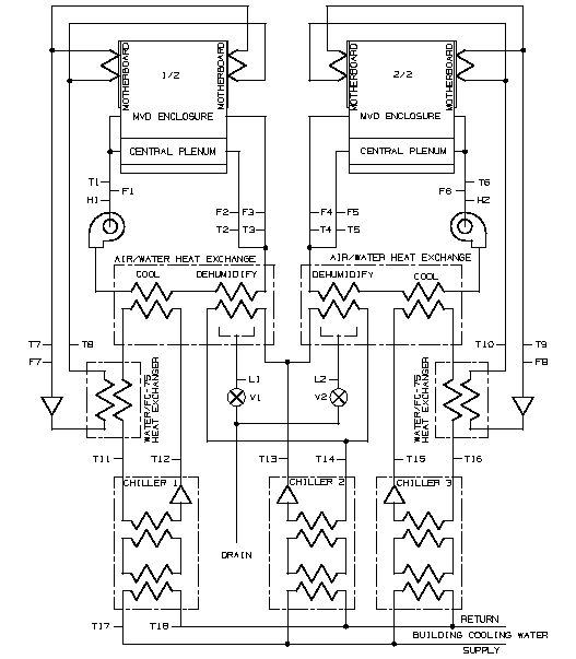
Below is a sketch of the MVD cooling systems. The East and West halves are drawn separately. There are 2 air loops and one liquid cooling loop. T1-T18 are temperature sensors, F1-F8 are flow sensors, H1-H2 are humidity sensors, and L1-L2 are liquid level sensors.
Postscript version