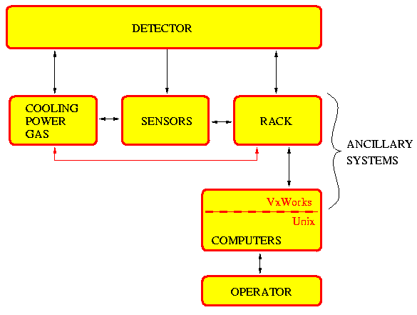
When a failure develops in the hardware, that is, the detector itself or the power, gas or cooling systems, there should be enough sensors around to pick this up. These sensors typically report to some rack in the area, from where their readings are available to the operator through a chain of processors, typically the ones that constitute EPICS.
The detector, cooling, power and gas are controllable by the operator via the computers, but critical components should be switchable by the hardware in the rack without the assistance of any software (red arrow).
This requirement influences the choice of sensors, and the details of power (gas, cooling) distribution.