Postscript version
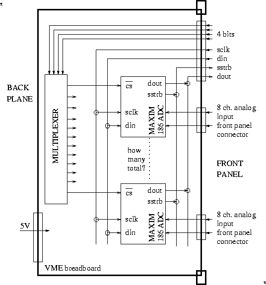
VME board layout. Essentially this is a copy of the hardware on the MVD motherboard. As drawn here, there are 16 (16 because of the 4-bit address multiplexing chip) 8-channel ADC chip from Maxim on the board, for a total of 128 single-ended readout channels. The ADC chips can be operated in differential mode, in which case there would be 64 channels. The board should be configured such that the mode can be selected with a jumper. Also, near the input points, there should be options to insert the proper noise-suppressing caps-to-ground, and allow for various grounding options.
In the figure, the input is via the front panel. This can be changed to have the inputs coming in from the back, perhaps with a small number copied to the front for testing purposes.
The top 8 lines on the front panel are driven by a digital I/O board in the VME crate (such as one of these). This board in turn is driven by a C-routine running in the MVME162, which in turn is activated as an EPICS subroutine record.
Using a 64-pin I/O board one of these). , one can service 1024 channels in 9 VME slots. The cost for the I/O module is about $575, while a wild guess of the custom board comes to somewhere under $1000, so that the cost per channel is expected to be less than $10.