
TR becomes useful when particle Lorentz-factor is greater than approxmately 1000. In this case emitted photons are in X-ray range (several keV) and can be detected by, for example, proportional chamber (Time Expansion Chamber (TEC) in the PHENIX experiment). In a very broad range of momenta (from 1 to 100 GeV) transition radiation is emitted only by electrons, which makes it a unique tool for electron/pion separation.
Typical Transition Radiation Detector consists of a radiator (dielectric foils, foam or fibers in gas) and an X-ray detector (e.g. proportional chamber).
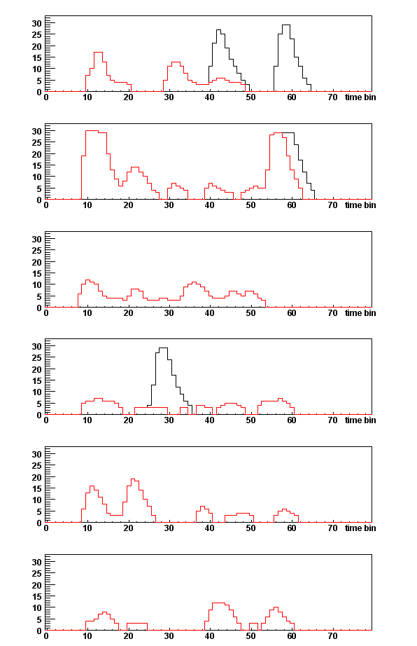
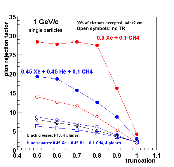
Unless explicitly mentioned, simulation was done for gas gain in TEC = 3000 and all 6 TEC planes active.

For a foil one has to sum up the contributions from the two interfaces:

TR yield from an irregular stack of dielectric layers was first calculated by
G.M.Garibian et al., Sov. Phys. JETP 66 (1974) 552
G.M.Garibian et al., NIM 125 (1975) 133

where I is a factor taking into account interference and absorption. I is a rather complex function, and the reader is refered to the above mentioned references for details.
G.M.Garibian et al. made their calculations assuming that the radiator is in vacuum. Their formulae were generalized for an arbitrary medium by:
M.N.Mazziotta, e-print http://arxiv.org/pdf/physics/9912042 (1999 )
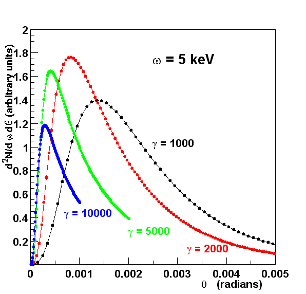
Angular distribution of TR X-rays for different Lorentz-factors (gamma)
is shown in the plot below. Theta is the angle
between TR X-ray and the direction of the particle.
The distribution depends on X-ray energy and is peaked at approximately 1/gamma.
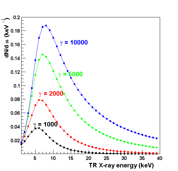
TR X-ray yield vs energy for different Lorentz-factors, numerically integrated over all theta angles, is shown in the plot below:
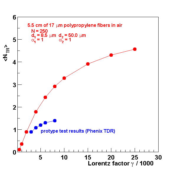
Average number of TR X-rays is shown vs Lorentz-factor gamma in the plot below for
one TRD/TEC plane in red points. Blue
points
show the results of the prototype test from PHENIX TRD (1993).
The difference
is explained by the fact that only 120 radiator foils were used in this test.
Similar plots for other gases:
0.9 Xe + 0.1 CH4 (density 5.36e-3 g/cm^3)
Air (density 1.205e-3 g/cm^3)
Solid polypropylene (CH2) (density 0.90 g/cm^3)
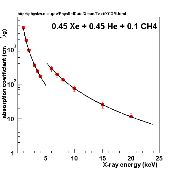
The plot below shows the fraction of remaining TR X-rays vs depth in
0.45 Xe + 0.45 He + 0.1 CH4 gas mixture for different X-ray energies:
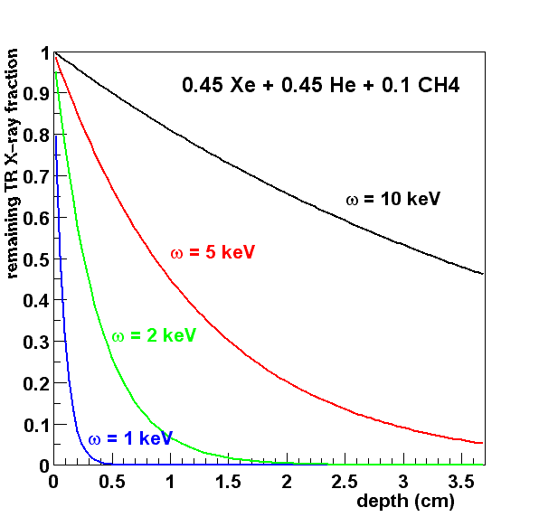
For 1 GeV/c electron 64% of TR X-rays or 49% of all TR energy are absorbed in 6 TEC planes. In case of 0.9 Xe + 0.1 CH4 gas mixture, 88% of TR X-rays are absorbed (77% of TR energy).
Absorption plot for 0.9 Xe + 0.1 CH4 gas mixture.
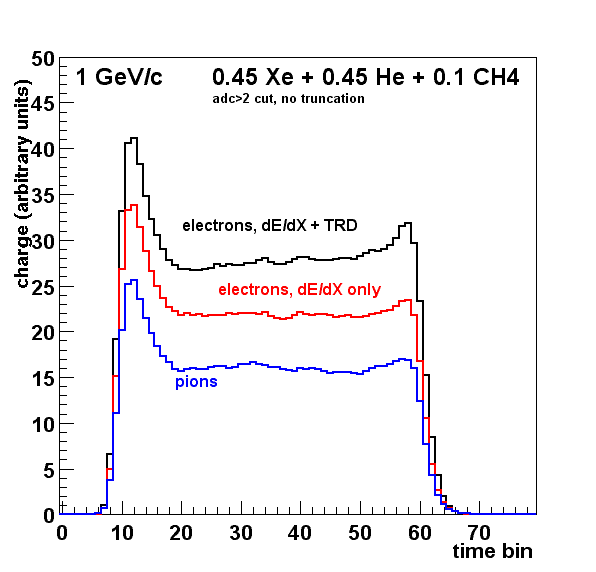
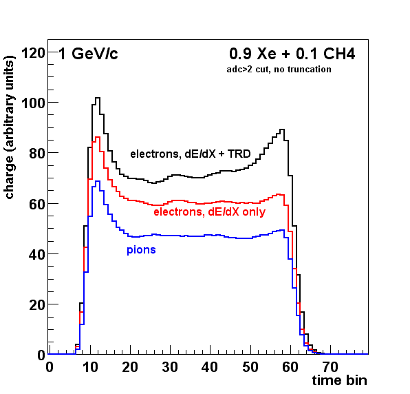
Charge in both plots is in arbitrary unit, but the two plots are normalized
relative to each other. As you can see, for Xe/He mixture the signal is more than two times
less than for pure Xe.
List of TR articles by A.Andronic
| Last updated 1/9/2003 by Sasha Lebedev |