MuID Safety Review Packet
September 11, 1997
Introduction
The purpose of this packet is to provide information to the RHIC
Safety Committee for the purpose of reviewing the PHENIX Muon
Identifier (MuID) from the standpoint of safety. Included in the
packet are MuID
background materials and summaries of the mechanical, fire and
electrical safety issues (there are no lasers, confined space access,
radioactive sources or magnetic fields). Relevant material safety data
sheets (MSDS) and product specifications will be made available in the
hardcopy version of this document.
Action Items from Previous MuID Safety Review
(February, 1997)
- Documentation from the machine group at RHIC is necessary to
assure concurrence with maintenance of DX magnet access.
The MuID does not
violate the MuID steel envelope which was designed to allow access to
the DX magnet (and which is already in place). Responsibility to
assure concurrence has been assigned within the RHIC machine group.
- Plans for the support structure and installation are at the
preliminary design review stage.
These issues are addressed with plans and drawings that, for the
most part, are in a very mature state.
- Bench tests will be done to determine the leak rate from the
prototype tubes at ORNL and Kyoto University.
This issue is addressed.
- Provisions to purge the cans should be added in the mechanical
design.
This issue is addressed, although plans for what to do with the
purged volume are only in a conceptual stage.
- Plans for the associated electronics on and away from the
detector, low voltage supplies, power dissipation, fusing, and cooling
should be reviewed.
The portion of these issues relevant to the panel interiors are addressed.
- Electrical grounding plans should be provided.
This issue is addressed.
- The cable plant should be addressed.
This issue is addressed, although not in final form.
- Detector operating and maintenance procedures should be submitted
and approved.
This issue is not addressed.
MuID Introduction
The PHENIX Muon Identifier (MuID) serves to distinguish between pions
and muons that exit from the back of the Muon Arm magnet. The MuID is
a sandwich consisting of several layers of steel absorber and
sensitive elements. The absorber preferentially stops non-muons and
the sensitive area records the remaining particles. The MuID operates
in concert with the Muon Tracker (MuTR) which accurately measures
particles' momenta before they enter into the MuID steel absorber
which would seriously degrade a momentum measurement. To orient the
reader, a picture of the PHENIX hall is shown in figure 1, below. It
may not be completely obvious from the picture, but the MuID will be
buried behind the PHENIX shield wall. This means that it must be in place
before the shield wall goes up (hence the scheduling urgency) and the
panel interiors cannot be serviced afterwards.
Figure 1. The PHENIX hall. Note the two muon arms north and
south of the central detector. For MuID, both arms are identical.
MuID Panels
The MuID consists of sixty physically separate detectors, called
panels. Large panels (40 total) are roughly 5.4 x 5.6 x 0.08
m3 and small panels (20 total) are roughly 2.9 x 4.3 x 0.08
m3. The panels are boxes which have edges formed by
specialized aluminum extrusions and covers made of 0.100" thick
aluminum covers. There is also a 0.125" thick aluminum mid-plane
(bisecting the panel volume in the short dimension). The box structure
serves as a fixture on which to mount the sensitive elements (Iarocci
tubes, described below) and some readout electronics, and as a
secondary gas containment vessel that we can purge if there are leaks
from the Iarocci tubes (which operate with an Isobutane/Carbon Dioxide
gas mixture). There are isolated signal, power, HV and gas connectors
at the edge of the panels to connect to the outside world. Figure 2
shows a full-scale prototype panel in a horizontal (for assembly)
position.
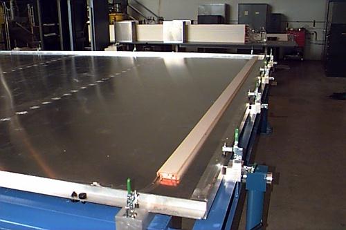
Figure 2. Full-scale MuID prototype panel at ORNL, shown in
its horizontal (assembly) position. The tubes shown are mounted to
the panel mid-plane. The panel gets flipped so that the other side of the
mid-plane is exposed (and the tubes shown are on the bottom side) and a
series of tubes are mounted in the orthogonal direction.
Iarocci Tubes
The detector technology chosen for the MuID sensitive elements are
Iarocci tubes. Iarocci tubes are a relatively standard HEP detector
consisting of wires, under high voltage, together with a preformed
cathode, all contained inside a hermetic gas volume. Our cathode and
gas volume are made of PVC (MSDS included). The PHENIX tubes are 8.5
cm wide with lengths varying from 2.5 - 5.2 meters. A picture of a
very short (~4") Iarocci tube without its hermetic gas volume is shown
in figure 3, below. The Iarocci tubes and the mating European HV pin
connector have already received safety approval.
Figure 3. A short (~4") Iarocci tube. HV, signals and ground are
connected through pins in the orange endcaps and the mating European
HV pin connector (shown at right). The black "comb" is the
cathode. The anode wires (probably not visible) are strung parallel to
the cathode comb, centered between the tines.
Summary of MuID Panel Construction Materials
This list only contains combustible materials inside the panels. The
Iarocci tubes are made of PVC (MSDS included). The total PVC volume
per panel is (large panel: 0.75 m3, small panel: 0.3
m3). There is internal cabling for HV, signal, power and
pulser (product specifications included). Cabling details are given
below, but note that all chosen cables pass the VW-1 vertical flame
test. In addition the signal cables (which are the bulk of the cable
volume) pass the N.E.C CL2 test. The total cable volume per panel is
(large panel: 0.12 m3, small panel: 0.1
m3). There is polyethylene tubing for gas distribution
(MSDS included). The total polyethylene volume per panel is (large
panel: 8000 cm3, small panel: 2000 cm3). There
is a foam tape (MSDS included). The total foam tape volume per panel is (large
panel: 16000 cm3, small panel: 8000 cm3). There
are small volumes (<1000 cm3 per panel) of other
miscellaneous tapes: kapton, double-sided, vinyl and fiberglass tapes
(MSDSs included for foam, double-sided, and fiberglass tapes). There
are a few cm3 per panel of epoxy (RHODORSIL Resin #991; MSDS
included) for gas sealing at the Iarocci tubes. There are several
dozen cable ties per panel. There are a few plastic connectors on the panel
edges to connect electrical services to the outside world (for signal,
HV and power; large panels: 8, 2 and 8, small panels: 5, 1, and
4). The signal and power connectors have a UL 94V-0 flammability
rating. Product specifications are included for all connectors. There
are printed circuit cards for HV distribution and signal
amplification. We have not included product specifications for the
various components. We have included MSDSs for two possible HV potting
compounds (G.E. Silicone's RTV 12 and Glyptal 1201B). The RTV is a
two-component silicone rubber (RTV12A is the rubber, RTV12C is the
curing compound). If we go with RTV12 the total volume per panel is (large
panel: 4500 cm3, small panel: 2250 cm3). If we
go with Glyptal 1201B the total volume per panel is (large panel: 180
cm3, small panel: 90 cm3).
DX Magnet Access
The MuID steel overlaps the DX magnet, but the panels do not violate
the boundaries of the hole in the MuID steel that was designed to
allow for access to the vacuum pumps for maintenance and removal if
necessary. This is shown in figure 4 below.
Figure 4. This figure shows three of the muon identifier
panels hanging in a gap (all gaps are identical). The six panels in a
gap hang in two parallel rails attached to the MuID steel. This figure
shows panels A,C and E, all of which hang in a single rail. The green
square at the center is the cutout to allow access to the DX
magnet. Note that the panels are contained within the MuID steel
envelope.
MuID Installation
The MuID panels will be constructed in a factory on the BNL site
(building 905). Bill Stokes or Jacques Negrin will summarize a finite
element analysis that they performed to validate the strength of the
panels themselves and the unistrut rails. The panels will be
transported from the factory to the Major Facility Hall (building
1008). At this point they will be installed in the permanent support
structure which will be attached to the MuID steel absorber.
There are unistrut rails that are critical to the operation of both a
specialized lifting fixture and the permanent support
structure. Figure 5 shows a closeup of one of the support rails in the
permanent support structure and gives details on the pull-out
reinforcements and can be followed along with the text
description. These rails are made of standard Unistrut Product P5501
which is two back-to-back pieces of 15/8 inch
sections. There are side plates attached to the rails to further
increase the safety factor on pull-out. The unistrut rails are
attached to a supporting I-beam (in the case of the lifting fixture)
or square tubes (in the case of the permanent support structure) with
unistrut nuts in the top column of the rail. Panels have cam
followers on their top bars that allow them to roll into the bottom
column of the rail. (The top of the bottom panels are connected to an
aluminum bar with the necessary cam followers with 5 meter steel
tubes. This allows the bottom and top panels to be supported in the
same rails.) There are stops in the rails to prevent panels from
rolling out. The top column of the lifting beam's unistrut rail is
filled with a piece that acts like a key and which fits into a lock
formed by the top column of the mating rail in the permanent support
structure. This ensures alignment and continuity. Analyses of the
lifting beam and permanent support structure are included in the
hardcopy of this document. These analyses were performed with a factor
of three safety margin from the yield point.
The MuID panels are only self-supporting when in a vertical position
and supported from their top rail. When they are not in such a
position they must be locked into a "strongback" - a self-supporting
frame. Together the panels and strongback will weigh less than 5000
pounds. Supported in such a strongback, the panels will be transported
from the factory to the major facility hall in a horizontal position
on top of a standard ball-hitch flat trailer. Once inside 1008 the
panel and strongback will be lifted together by the main crane
(15/20/40 ton) using an eye hook welded into the strongback. Together
they will then be placed on a vertical dolly which will hold the
strongback/panel combination with pins inserted into the
strongback. The above-described lifting fixture will then be rolled
onto the panel where it is held with the main crane. The panel will
then be released from the strongback (which will still be secured to
the vertical dolly) and lifted by the main crane via the lifting
fixture into position aside the unistrut rail in the permanent support
structure. The mating unistrut rails of the lifting fixture and
permanent support structure are locked together and their level is
verified. At this point the panel will be rolled from the lifting
fixture into the permanent support structure, and the lifting fixture
will be returned to the floor.
Figure 6 shows a rotated full-length view of the panels supported in the
permanent support structure. Figure 7 shows a closeup of the supported
panels. These are slightly dated figures, so Gap 6 is shown even though
this gap will not be instrumented.
Figure 5. This figure shows the design details of the
reinforced unistrut rails that hold the panels in their final
positions.
Figure 6. This figure shows a rotated view of the
entire height of one arm.

Figure 7. This figure shows details of the attachment of the
panels to the MuID steel and the placement of chambers in the
gaps. Three different positions for the steel are shown: 1) where it
was supposed to go, 2) where it was actually installed in the north
arm, and 3) where it was actually installed in the south arm (the
width shown indicates the smallest and largest z-excursions). For gaps
2 and 6, the small panels are shown, for all other gaps the large
panels are shown. Gap 6 will not actually be instrumented.
MuID Gas System
We will use a mixture of Isobutane/Carbon Dioxide with a maximum
isobutane concentration of 50%. Gas will vented into the atmosphere -
there will not be a recirculating system. The total gas volume of the
detector is 50 m3, although the gas volume of the largest
individual panel is <1 m3. Normal operation will require a
maximum flow rate of 50 m3 / day (35 l/min), assuring one
volume gas exchange per day. The panels will operate at pressures very
slightly above atmospheric pressure (~10 mbar). They can withstand a
60 mbar overpressure without inflating/deforming too much (a safety
factor of 6). The gas system will be designed (with bellows, etc.) to
track ambient pressure. These may appear to be small pressure
differences but the volume (25 cubic meters / arm) is very large
While the gas mixing system has yet to be designed, it is understood
that this will reside outside the collision hall. The gas distribution
system requires that gas is presented in a manifold at the edge of a
panel and then distributed in parallel using polyflow tubing to groups
of 24 tubes each. (This gives 12 gas circuits for a large panel and 6
for a small panel.)
Leak tests were performed on tubes from the selected tube
vendor. After proper tightening of the gas connectors at the edge of
the tubes a chain of 22 tubes was pressurized to 30 cm H2O
and attached to a manometer. A pressure drop of 1.7 cm was observed
over a period of 29 hours. This represents a leak rate of
approximately 1.6 cm3/hr/tube.
The tubes will be pneumatically leaktested at the manufacturer by
placing them under a foot of water and demanding that there be no more
than two bubbles of gas per minute leaking out of the tubes. We
estimate this to be a leak rate of 0.6 cm3/hr/tube. After
the tubes arrive at BNL, but before they are installed in the panels,
the tubes will be pneumatically leaktested with a manometer system
similar to that used for the leak test described above. Each gas chain
(including all internal distribution) will be similarly leaktested
before the panels are installed in the major facility hall. We can
make this pneumatic leaktest arbitrarily sensitive by observing the
pressure loss over an arbitrarily long time. But by demanding less
than a 1 cm pressure drop over 16 hours we limit any leaks to be less
than 1.6 cm3/hr/tube, or 400 cm3/hr/panel (0.016
ft3/hr/panel).
As recommended by the tube manufacturer, gas connectors on the tubes
will be sealed with RHODORSIL Resin #991 in order to prevent leaks
from developing over time (in a manner similar to teflon tape).
The panel frames serve as secondary gas containment vessels. The panel
edges are designed to allow for a constant purge of the secondary
containment vessel with room air at a rate sufficient to remove
accumulated residual gas and render it non-flammable. Although the
purging system has not been designed, the concept is to feed the
purged volume into gas sensors that will detect the presence of
chamber gas in the purged volume.
MuID Electronics
Summary of Electrical Hazards
HV: 5000 V with currents software limited to 100 uA/line.
Stored Energy (on HV capacitors): 1.5 J/ HV line.
Power: +/- 12V with 0.2 A/line.
High Voltage
The MuID high voltage system feeds an identical
partitioning as the gas system to both muon arms (i.e., ~24 tubes per
control). The operating voltage is 5000 Volts and the expected current
is <1 micro amp per tube. A LeCroy HV supply will be used that
provides a maximum of 6000 Volts per channel at a maximum current of
100 micro amp. The latter will be limited by software control at the
supply. 400 MOhm resistors on each tube will passively limit the
current to 12.5 micro amp per tube. External HV cables have not been
chosen yet. We know they will be multiconductor cables made from
appropriate HV corona resistant wires. The HV cables enter the panel
through isolated feedthroughs (2 per large panel, 1 per small panel;
AMP 15 kV Seven-Pin Metal Shell Circular Connector
(862004-1)). Internal HV distribution will be through corona-resistant
AWG 20 HV wire (Rowe Industries R1800-1520). This wire passes the VW-1
vertical flame test. The HV lines will be secured to the mid-plane
with occasional cable ties. They will be physically isolated from
signal and power lines both inside and outside the panel. Product
specifications for wire and connectors are included.
Power and Fusing
There are in-panel amplifiers (described
below) that will require low-voltage (+/- 12 V) power supplies. The
power system feeds an identical partitioning as the gas and HV
systems. Large panels will have 6 lines (small panels 3 lines) at each
voltage, each of which will carry 200 mA. Power on each line will be
fused at the supply. The power supplies have not been chosen, nor has
the distribution to the panel. Power cables enter the panel through
isolated feedthroughs (AMP 206061 and associated pins/sockets and
cable clamps). Internal power distribution will be via four-conductor
AWG 22 cable (Dearborn 882204) secured to the mid-plane with
occasional cable ties. The four conductors carry +/-12V and grounds
from each supply. The wires pass the VW-1 vertical flame test and the
connectors have a UL 94V-0 flammability rating. Product specifications
for wire and connectors are included.
Signal Cables
Signal cables will go out to front-end
electronics via multiconductor shielded twist-and-flat cable (Belden
9M28334). The design of the front-end electronics is only just
beginning, so they will not be addressed here. The cables exit the
panel through an isolated feedthrough (3M 4634-7300). Internal
distribution of signals will be through the same Belden cable secured
to the mid-plane with occasional cable ties. The signal cable passes
both the VW-1 Vertical Flame Test and the N.E.C. CL2 test. The
connector has a UL 94V-0 flammability rating. Product specifications
for cable and connectors are included.
Test Pulser
There is a test pulser capability built into the
in-panel amplifiers. This requires 2 lemo connectors per large panel
and 1 Lemo connector (HGW.00.250.CTLP) per small panel; and less than
10 meters of RG174 cable (Alpha 9174; passes VW-1 vertical flame
test). In addition, large panels require 2 (small panels 1) additional
power connectors, as described above.
In-panel Amplifiers/HV distribution
There are printed circuit
cards for high-voltage distribution and signal amplification mounted
on the panel's mid-plane. Figure 8 shows a schematic of the board
layout. Figure 9 shows the mounting scheme. Click here to see a closeup of one corner
of the panel showing how the preamps attach to the Iarocci tubes,
where the cables are, etc. Click
here to see the in-panel HV/amplifier circuit diagram.
Each card services six pairs of Iarocci
tubes - several cards will be jumpered together to form HV and power
busses to service the dozens of pairs of tubes in a panel. The jumpers
are short (few inch) pieces of insulated wires that connect solder pads on
the distribution busses of two different cards. The HV jumpers are
made from the same HV wire as the rest of the internal HV
distribution. Other jumpers are made from AWG 22 hookup wire (Alpha
1551; passes VW-1 vertical flame test).
The HV distribution portion of the board will be laid out according to
the Institute for Interconnecting and Packaging Electronic Circuits
specification #IPC-D-275 which defines the required spacing for DC
voltage differences between conductors on pc boards to be 0.00012
inch/Volt. HV is delivered from the cards to the Iarocci tubes by way of a
flying lead (a 6" jumper made from the same HV wire as the rest of the
internal HV distribution) connected to the mating European HV pin
connector. The signals are read from the anode wire, capacitively
decoupled. The solder joints connecting the jumpers and the flying
leads to the card (all pads, no plated-through holes), along with all
other HV components, will be potted in an isolating compound. Although we
have not chosen an isolating compound at this moment, two look
promising: GE Silicone's RTV-12 and Glyptal 1201B. This
potting is more for protection of the electronics than for
protection of people because the HV side of the board will be mounted
facing the aluminum mid-plane, so that all HV components are
thoroughly inaccessible. Furthermore, we do not anticipate needing to
operate a chamber without its coverplates which further isolate the
amplifiers behind an aluminum wall.
There are a maximum of 26 channels on an HV chain, each of which has
two 2.2 nF HV capacitors plus the tube capacitance of roughly 0.5
nF. At 5000 V, this adds up to a maximum stored energy in each line of
1.7 J. This is significantly below the threshold of 10 J, but to
prevent unnecessary shocks the HV inputs will have a 1 GOhm bleeder
resistor to ground in parallel with the Iarocci tubes. This
effectively short-circuits the caps, discharging them with a time
constant of 7.5 sec after the HV supply is shut off.
Figure 8. Layout of the MuID amplifier/HV distribution card
showing board-to-board jumpering and the flying leads. HV and
power/amplification components are shown to be on opposite sides of
the board.
Figure 9. Mounting scheme for the MuID amplifier/HV
distribution card. The solder joints (all pads, no plated-through
holes) connecting the jumpers and "flying leads" along with all other
HV components will be potted in an isolating compound. This side of the board is
then mounted facing the aluminum mid-plane, so that all components are
thoroughly inaccessible.
External Cable Plant
Since the external cables have not been
finalized, the external cable plant cannot be finalized. But, we can get a
good idea of the sizes involved. We assume for this purpose that the
internal and external cables will be identical. Each arm has a total
of 210 signal cables (0.41" diameter each), 50 HV cables (~0.4" diameter each)
and 150 power cables (0.18" diameter each). Front-end electronics and
power/HV supplies will likely be located along the west wall of the
Major Facility Hall and to get there will require cable lengths of
5-20 meters depending on the panel.
Grounding
All panel grounds will be isolated from the aluminum
box which is electrically attached to the MuID steel through the rails
from which the panels are hanging. Each multiconductor HV cable has
one AWG 20 ground wire. Each multiconductor power cable has 2 AWG 22
ground wires. Each signal cable has 2 AWG 28 ground wires. HV, signal
and power ground wires will all be connected at the panel. The HV
ground wire will be connected to earth ground at the HV supply. Power
grounds will not be connected to earth ground at the supply and signal
grounds will not be attached to the FEM grounds.
Cooling
Cooling is not an issue for the panels - the amplifiers
on a panel side will dissipate 11 Watts; their area is 4
ft2. External cooling requirements are not addressed.
Enclosures
- PVC MSDS.
- Polyethylene MSDS.
- RHODORSIL Resin #991 MSDS.
- MSDSs for HV potting materials.
- MSDSs for double-sided, foam, and fiberglass tapes.
- Product specifications for wiring and connectors.
- Summary of engineering analysis of panel lifting beam and
in-experiment support rails.
- In-panel amplifier/HV distribution circuit diagram.
- In-panel amplifier layout.